FWIW, I found that using a linear class 2 wall wart PSU typically found on old routers ideal for this preamp. 12v 1000mA or 800mA works too. Step up to 52v then you get 48v our after the cap Mx. If you can find a 48v to 55v linear regulated PSU - even better - then you can skip the DC-DC. They are big and expensive though.
IHB48-0.5 - International Power - Linear Power Supplies | Galco Industrial Electronics
You could also make your own unregulated one with a 10VA trafo from Antek, a rectifier bridge, a 9600uF cap and feed that to the onboard cap Mx. Precise voltage is not necessary but good to have about 45v to 48v at input to actual amp daughterboard.
Last edited:
FWIW, I found that using a linear class 2 wall wart PSU typically found on old routers ideal for this preamp. 12v 1000mA or 800mA works too. Step up to 52v then you get 48v our after the cap Mx.
I can confirm that it works very well. As X has noted before, if mounted inside the chassis, it's not class 2 anymore, but who cares? I'm very happy that I've decided to mount a router linear PSU internally. It gets hot, though - so ventilation slots is a must.
It wouldn't be that hard to make a simple regulated supply using a TL783. With some tweaks that regulator could be used in place of the cap Mx on the mother board. Would something like that be better option over the 48Vdc SMPS?
Well, before I begin building the power supply the daughter board needs to work. I am measuring 20vdc on the input of the card. I double checked my transistors and they are in the correct spot and check out with the diode function on the Fluke.
Hi Skylar,
Wow, that’s a beautiful preamp! One of the best looking that I have seen. I know it sounds awesome too.
Congrats!

Wow, that’s a beautiful preamp! One of the best looking that I have seen. I know it sounds awesome too.
Congrats!
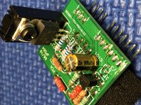
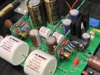
I started assembling the new PCA daughter boards that member Twocents requested, and instantly a nice compact layout by JPS64 magically appeared!
I’m also able to use one of the Crown Jewels in my parts bin (2SK170) because GaryS had suggested that option 🙂
It’s a very easy low parts count board to make, but it took some tweaking to get the bias current across the quad paralleled resistors just right. Voltage after the onboard capMx is 21vdc and across the quad paralleled resistors is 11.6vdc.
I started at the 270R value from the schematic- WAY to hot!
Next up was 330R, better but still to hot at 127mV
Then up to 470R, almost there at 98mV
Last stop will be 560R, unfortunately I’m out of them now. A quad paralleled set of 560R will give a total resistance of 140R and that will bring down the bias current to approximately 83mV.
I haven’t listened to music yet, so I have nothing to comment on there.....
This Aksa Lender Pre is setup for strictly preamp duty, no HPA use.
Attachments

Nice work, Vunce! That’s a good looking board. Do you mean mA and not mV?
When you say hot, is the MOSFET too hot or the resistors too hot? If resistors hot, try using a pair of 1W resistors in parallel which should comfortably dissipate 1aw.
When you say hot, is the MOSFET too hot or the resistors too hot? If resistors hot, try using a pair of 1W resistors in parallel which should comfortably dissipate 1aw.
Thanks X.
It was late when I posted, yes I meant mA 😀
I can’t pull those late nights as successful as you, lol!
The resistors seem fine, it’s the Mosfet I want to run a bit cooler.
I’m finishing up the second board now and have the resistors set up just right for a paralleled value of 137R5
It was late when I posted, yes I meant mA 😀
I can’t pull those late nights as successful as you, lol!
The resistors seem fine, it’s the Mosfet I want to run a bit cooler.
I’m finishing up the second board now and have the resistors set up just right for a paralleled value of 137R5
You can use a bigger heatsink - it’s ok for them to run 85C even - just be careful touching it. Electronics are fine at those temps relative to lifetime and all.
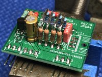
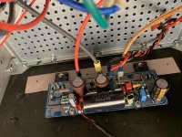
My Aksa Lender preamp stuffed with PCA DB’s is singing away!!
Sounds really good, Mosfet heatsinks are running 55°C.
Now time to enjoy the make-over 🙂
Sounds really good, Mosfet heatsinks are running 55°C.
Now time to enjoy the make-over 🙂
Attachments
Thanks Hugh 🙂
It’s amazing how so few strategically placed components on the PCA board can sound this good.
Next up will be the Yarra PCA’s.
It’s amazing how so few strategically placed components on the PCA board can sound this good.
Next up will be the Yarra PCA’s.
Very nice work, Vunce. What amp are you driving with it? It will transform a so so Class AB amp into a real knock out. Almost “tube like”. 🙂
Hey X, Thanks!
I’ve got the ALP driving my SLB powered Alpha20 amp.
A full AKSA tandem if you will 😀
I’ve got the ALP driving my SLB powered Alpha20 amp.
A full AKSA tandem if you will 😀
I think he meant fired up. 2.35A is a higher setting than usual 1.3A so are you planning on using with 4ohm speakers?
It usually warms up pretty fast so that it doesn’t sound distorted after like a few second. Not like the M2 which takes like 40 seconds and you definitely hear the distortion as it warms up.
What is your DC offset? If that’s all good and it’s holding a steady bias current then it should play music.
It usually warms up pretty fast so that it doesn’t sound distorted after like a few second. Not like the M2 which takes like 40 seconds and you definitely hear the distortion as it warms up.
What is your DC offset? If that’s all good and it’s holding a steady bias current then it should play music.
I must have been fried last night when I posted that! This isn't even the correct thread for the Alpha... 
The DC offset is 18mV, no hum was present and no turn off/on noises! The distortion lasted a longer than I expected it would; long enough for me to remove it from the variac and plug it directly into the main. I was not driving a 4ohm speaker with them during the test. Would that contribute to any distortion?
I purchased the PCB, along with the parts to build the higher biased 4R version. When I populate the second channel I will set it for the lower biased 4R version and compare them before making them same.
Regarding the pre-amp, which is this form is actually about, I am having some trouble getting the SMD daughter board to work. I think have the proper voltage on the input, but nothing on the output or on the base of the diode. Maybe the mosfet or a BJT got zapped 😕
Hi Shawn,
Sorry you are having trouble with the Aksa Lender daughter board.
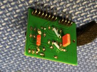
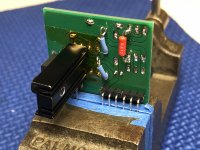
Best thing to do is to get some female pin connectors that will allow you to power up the daughterboards outside of the main board on your lab bench.
Use a voltmeter referenced to GND (0v) and probe each node in the circuit especially each pin of each transistor - write this down directly in red ink on the schematic. Take a photo of it and post here. We can debug it for sure this way. It’s a complete diagnostic leaving nothing (well almost) to guessing.
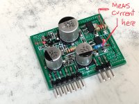
Besides zapping the BSP129 depletion MOSFET, I would check for cold solder joints and double check resistor values. Retouch all solder points with iron to flow.
If you have bias current across the source resistor on the output stage circa 25mA to 45mA and voltage at output is about half Vcc, you are good. These are the R116/117 as shown in photo.
Also check to see if you have about 2mA bias current across either leg of the input LTP.
Make sure you did not forget to install the tiny little diode next to the cap in the top left corner.
Sorry you are having trouble with the Aksa Lender daughter board.
Best thing to do is to get some female pin connectors that will allow you to power up the daughterboards outside of the main board on your lab bench.
Use a voltmeter referenced to GND (0v) and probe each node in the circuit especially each pin of each transistor - write this down directly in red ink on the schematic. Take a photo of it and post here. We can debug it for sure this way. It’s a complete diagnostic leaving nothing (well almost) to guessing.
Besides zapping the BSP129 depletion MOSFET, I would check for cold solder joints and double check resistor values. Retouch all solder points with iron to flow.
If you have bias current across the source resistor on the output stage circa 25mA to 45mA and voltage at output is about half Vcc, you are good. These are the R116/117 as shown in photo.
Also check to see if you have about 2mA bias current across either leg of the input LTP.
Make sure you did not forget to install the tiny little diode next to the cap in the top left corner.
Attachments
Last edited:
- Home
- Source & Line
- Analog Line Level
- AKSA's Lender Preamp with 40Vpp Output