The back-EMF is pronounced at resonance primarily. This is why the damping of the resonance peaks by parallel R is effective in reducing audible coloration. . Same reason for the 'motional' fb approach I used many decades ago and JR has found makes a difference. I agree the main rise in L at higher freq is Ls. A rework of JR formulas is needed thus to be a better fit to reality. [could not stand this 'EE' issue dragging on any longer] Yes, JC, if 2 or more people hear something the same way, it is there and it is real. Just have to figure it out as to what is happening.
THx-RNMarsh
THx-RNMarsh
Last edited:
Ummm. So what?
Measure the group delay instead. More insightful.
-RNM
It was you who said that EE would measure "cable resistance" and said it has no effect. It has a small effect which can be seen from the measurement and it depends on length and impedance of the cable, as everyone knows. For home installations the effect is very small.
"Measure the group delay instead" is just another empty phrase of yours. Every SW like REW shows it.
I am looking forward your measurements instead of haughty comments. You have not shown much yet.
Of course. It is only a continuing game by RNM, meaningless.Isn't group delay a derivative of phase as a function of frequency and therefore in the measurement already?
So during three months your sound degrades, why would you not apply contact treatment/oil and eliminate this recurring problem ?. What is the nature of the degradation and when does it become a noticeable problem, or to put it another way what is the nature of the subjective improvement after contact cleaning ?. Do all cables go back into same sockets and cables refitted in original directions ?All of my electronics have gold plated contacts. Every three months I unplug and wipe everything down with naphtha and replug - makes a huge difference in sound.
Ok, could you give a little rundown on what items are battery powered and how please ?. What is the nature of the degradation as the batteries sag/what is the nature of this huge difference when new battery is swapped in ?. What types/chemistries and capacities of batteries please ?.My rig is driven throughout by batteries, I have two sets and when one starts to falter, the other gets swapped in - again, a huge difference in sound.
I find that my system sound is stable, that said I run laptop on batteries, USB DAC and amplifier AC power filtering. Also usually the only electrical items operating in the house is the fridge, router/modem and some lighting, IOW there are no other AC power noise sources operating on the same AC supply circuit....no standby items, no chargers no nothing.If it is too hot or cold, or too dry or humid, the sound suffers. I have good and bad days, and so does my rig. Whether either can be, or even wants to be measured is debatable.
Dan.
And if output impedance of "normal" amplifier at speaker resonance frequencies is 0,01-0,1 ohm ( +cable impedance), how effective is added damping resistor, parallel to this output??🙄The back-EMF is pronounced at resonance primarily. This is why the damping of the resonance peaks by parallel R is effective in reducing audible coloration. .
THx-RNMarsh
Hey, a good question. I dont know. Other than i have seen THd measure very different at amp term and then at far distant speaker term (higher). I would bet a dollar that if you had 3 inches between PA and speaker, a shunt R would then make little or no difference.And if output impedance of "normal" amplifier at speaker resonance frequencies is 0,01-0,1 ohm ( +cable impedance), how effective is added damping resistor, parallel to this output??🙄
The addition of a 0.1 r in series and placed in PA fb path is also effective mostly at speaker resonance, only.
THx-RNMarsh
Last edited:
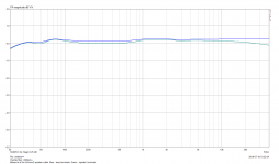
This is the effect of 6m, 2x4mm2 speaker cable to amplitude response.
Blue - amp terminals
Green - speaker terminals.
Wow, 0.1dB in the audio band and 0.3dB at 40kHz. Really "big" effect .....
What if one connects the beloved SET tube amp or a no feedback amp? 😀
Blue - amp terminals
Green - speaker terminals.
Wow, 0.1dB in the audio band and 0.3dB at 40kHz. Really "big" effect .....
What if one connects the beloved SET tube amp or a no feedback amp? 😀
Attachments
What if one connects the beloved SET tube amp or a no feedback amp? 😀
Probably be fine if your name is John Curl you only listen to simple music 😉
BR tuned at ~45 Hz?
Exactly, maybe 46, 47. Small 2-way column speaker.
I am happy for you. ?? Who is talking about freq response? Are you one of Those EEs? Stay focused, pls. What speakers do you have and is there a low freq speaker resonance? Show Z plot pls.This is the effect of 6m, 2x4mm2 speaker cable to amplitude response.
Blue - amp terminals
Green - speaker terminals.
Wow, 0.1dB in the audio band and 0.3dB at 40kHz. Really "big" effect .....
What if one connects the beloved SET tube amp or a no feedback amp? 😀
I have bi-amped JBL M2 at this time.
THx-RNMarsh
Last edited:
Now you are cooking! Now we can better understand the argument. Keep going....
I am especially interested in what you will say about resonance re. back-EMF. 🙂
THx-RNMarsh
Keep going indeed, please be patient with me as I try in a few words... this is quite a challenge.
That peak at 42 Hertz Fs (Free Air Resonance) is the motional impedance of the driver.
There are basically three types of back-EMF that explains the impedance above Re:
Motional back-EMF: This is simple to understand, motion of the coil in the magnetic gap is of course (I don't think there will be any disagreement on this) a voltage generator. Hence we have a voltage source. Note that this is back-EMF, and we know the EMF is a force or voltage. This is what forces the impedance up and peaks at Fs.
It opposes the current of the amplifier, it impedes the current of the amplifier, it is a measurable impedance, just deduct Re and you have it in Ohm value.
Inductive back-EMF: Rather than motion, this is current through the coil, this is Faraday's Law of Induction, this too opposes the current of the amplifier with increasing frequency. So when they say that the rise is caused by inductance, they are right, but I am describing the mechanism by which the impedance rises. Again we can calculate the impedance by deducting Re. Not that hard to understand.
Microphonic back-EMF: Does not always show up in the impedance plot, but typically they can be caused by bad resonances in the cabinet showing around 300-800Hz range. But this is maybe the worst kind of back-EMF. This needs the most detailed explanation. It is much broader in frequency and can appear anywhere, even if not so obvious in the impedance plot.
Imagine a 1KHz tone fed into the speaker, measure the AC current (put a meter in line with the driver). Imagine you could whistle into the front of the cone at exactly at 1KHz and match the phase (in phase) with that tone. Let us say you have 100mA of current from the amplifier and then start whistling, the louder you whistle, the 100mA of current will reduce. If you were able to whistle so loud that it would come down to 50mA, then at 1KHz you have changed the impedance that the amplifier is seeing. If it was 8 Ohm, it would now be 16 Ohm.
This thought experiment shows that the coil acting as a voltage source is a back-EMF that forces the impedance up because it opposes the current of the amplifier. By changing the impedance, the current is changed and the dB-SPL of the driver is changed.
I have used the above thought experiment and physicists, engineers and designers have understood it.
Now if you have a bad flaw, like a bad resonance in the driver, and it gets triggered, that will modulate the current of the amplifier, modifying a current with an ongoing resonance (they have a tendency to hang around or ring) we now have the distortion of the driver showing up in the current of the amplifier, but worse than that, being smeared in time.
The driver is a current device, output is proportional to current and not voltage.
F = BLi
Some amplifiers, for various reasons, will cope better with that smeared distortion. Tube amplifiers almost certainly do (one of tube's magic secrets?) and perhaps low feedback types as well. I will leave that discussions for others if they want to join in. Can we design amplifiers that might improve further?
What I do know is this:
The above scenario will not change the distortion of the amplifier? Not on the voltage side. This voltage tells us what we ought to be listening to, but the amplifier's current is more likely to tell us what we are listening to.
The maths and measurements I presented earlier (did it twice) absolutely shows that any change in dBSPL is due to current and current alone. Hence that is what the driver will produce and what we hear.
A resonance further modifies the current, any flaw, bad design will. Only the best drivers will do, and look for low inductance and flat impedance above 200Hz. A resonance loves the existing back-EMF impedance due to inductance and will modulate it, then modulate the amplifier. Once that is grasped, the pieces fall into place.
F = BLi
There is no exception to that. I am sorry if some here can't agree with that, but that is what the evidence tells us.
Thanks for the opportunity.
Cheers, Joe R.
Last edited:
This is the effect of 6m, 2x4mm2 speaker cable to amplitude response.
Blue - amp terminals
Green - speaker terminals.
Wow, 0.1dB in the audio band and 0.3dB at 40kHz. Really "big" effect .....
What if one connects the beloved SET tube amp or a no feedback amp? 😀
Newell/Holland reported in their book some results from Voishvillo, Terekhov and Czerwinski, showing the differences (spectral content;multione test signal) when using differently constructed cables in combination with different load conditions while using the same amplifier:
https://www.eetimes.com/document.asp?doc_id=1274851
And what are you expecting with nonlinear load driven from voltage source?? Linear current??Not on the voltage side. This voltage tells us what we ought to be listening to, but the amplifier's current is more likely to tell us what we are listening to.
@Jakob2 - Thank you, to me it looks like amplifier or measurement error or both (HF noise affected). I cannot confirm such results, I am not getting them like in the article.
BR tuned at ~45 Hz?
Exactly, maybe 46, 47. Small 2-way column speaker.
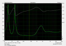
What speakers do you have and is there a low freq speaker resonance? Show Z plot pls.
THx-RNMarsh
As you can spot from the graph Pavel showed, it has a double resonance on the low end, indicative of a BR enclosure.
It shows because there are tiny (<<.2 dB) variations in the impedance plot, caused by a less than infinite damping factor in the preceeding chain. But it also shows it is a good amp, because, from experience, I know that such an impedance peak is usually at least 12 dB over Re.
On the whole, the larger the back EMF is at resonance of a driver, the better it is. The M2 will also show two impedance peaks on the low end. The second peak will be the highest, and in the case of this JBL high end speaker, it will be very high. The reason is that Harman knows that speakers with low Qms are best to be avoided.
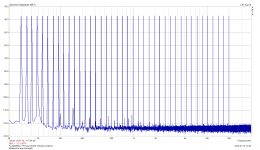
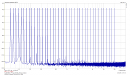
Briefly made some multitone measurement at amp terminals and behind the 6m cable at speaker terminals, cannot see much difference else than the wire loops are very different, so there is some change in mains components. Hundreds of mV peaks, I would need to measure by scope if needed.Newell/Holland reported in their book some results from Voishvillo, Terekhov and Czerwinski, showing the differences (spectral content;multione test signal) [/url]
Edit: multitone time plot attached
As you can spot from the graph Pavel showed, it has a double resonance on the low end, indicative of a BR enclosure.
It shows because there are tiny (<<.2 dB) variations in the impedance plot, caused by a less than infinite damping factor in the preceeding chain. But it also shows it is a good amp, because, from experience, I know that such an impedance peak is usually at least 12 dB over Re.
On the whole, the larger the back EMF is at resonance of a driver, the better it is. The M2 will also show two impedance peaks on the low end. The second peak will be the highest, and in the case of this JBL high end speaker, it will be very high. The reason is that Harman knows that speakers with low Qms are best to be avoided.
Here is the impedance plot. The small irregularity peak at about 220Hz was due to box standing waves and was damped later.
Attachments
Newell/Holland reported in their book some results from Voishvillo, Terekhov and Czerwinski, showing the differences (spectral content;multione test signal) when using differently constructed cables in combination with different load conditions while using the same amplifier:
https://www.eetimes.com/document.asp?doc_id=1274851
 .
.Looks like a quality bass driver in a well aligned enclosure.
Thank you, I appreciate your comment as you are specialized in speakers.
You are applauding to measurement and experiment errors.
Coherers were used as detectors in early radio. Their resistance changed due to signal, and they needed a mechanical thump to reset them. I understand that the detailed physics of how they work is still not understood.simon7000 said:In the microphone example mechanical motion may exist if the fault is at the microphone connector, but there are many other cases where it just signal doing it.
Relay contacts used in low level circuits (e.g. switching filters in a radio IF amplifier) sometimes need a DC 'wetting' current to keep contact resistance low.
How relevant this is to audio contacts I don't know.
That is just a private definition of a technical term. It contains no technical content.Joe Rasmussen said:Take any part of an impedance plot, at any frequency, the impedance above the Re value (the DC resistance of the voice coil) is the back-EMF impedance.
Pity you stand by it, because it is clearly wrong. The extra "impedance" of 9 ohms would only be true if it was in phase with the DC resistance, which you have explicitly said is not the case. Have you ever heard of complex numbers? Do you know how to do impedance calculations?So if you know the Re = 6 Ohm and the impedance plot says 15 Ohm @ 1KHz, then you know that the back-EMF impedance @ 1KHz is 15-6 = 9 Ohm. And yes, it is caused by current flowing through the inductive part of the impedance, and according to Faraday, becomes a voltage source. I stand by that.
Let us assume that the DC resistance is 6 ohms, and someone who does not understand impedance measures a total (modulus of) impedance of 15 ohms at some frequency and says that the extra is all inductive in origin. Then the correct calculation is that the extra impedance is given by sqrt(15^2 - 6^2) = 12ohms inductive.
How can we take you seriously when you can't even do basic electronics arithmetic?
Meanwhile, your fan club (some of whom should know better) cheers you on:
RNMarsh said:Now you are cooking! Now we can better understand the argument. Keep going....
- Status
- Not open for further replies.
- Home
- Member Areas
- The Lounge
- John Curl's Blowtorch preamplifier part III