thanks, chalky for your well detailed progress report, i bought the same boards and am buying components little by little. will keep following up on this thread 😉
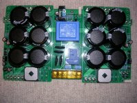
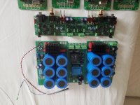
More progress. I've attached a photo of my nearly completed power supply and protection board. I'm going to fix heatsinks to the bridge rectifiers, and make up a couple of solid state relay pcbs to replace the loudspeaker protection relays. I'll make them with the same footprint and connections as the mechanical relays so that they are a drop in replacement on the main pcb. Initially I'll make them up on small pieces of perfboard and then later on I'll do proper pcbs.
Attachments
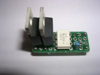
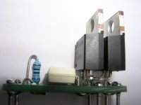
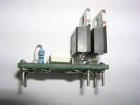
Got perfboard prototype of the solid state relay for loudspeaker protection finished today. It uses an Avago ASSR-V621-302E photovoltaic opto coupler together with a pair of FDP083N15A mosfets ( 150 V, 117 A, 8.3 mΩ ) in the "standard" circuit found all over this forum. The ASSR-V621 leds are connected in series and the photovoltaic outputs in parallel. I use a 680R series resistor to give a led current of 15mA. The polarity of the coil connections to the relays is immaterial for mechanical types but it matters for the solid state version. Unfortunately the designer of the main power supply/protection pcb has not been consistent in his choice of coil polarity connections and so two versions of the solid state relay are required - each with a different polarity for the "coil" connection. The module simply drops into the pcb in place of a mechanical relay.
Attachments
Hello again.
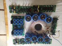
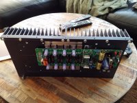
Chalky I see you're making progress, despite you been sick, work also stalled here due to work overload and sickness, well my boards are almost finished, just missing a few parts, input works fine, also psu board, I decided to make it 4 channel with bridging option, I got my hands on a fat 2kw toroid to power the beast, now my worries are finding a suitable large chassis to contain it all, pretty sure it's going to cost the tip of a jet plaine, anybody got it working yet?.
Chalky I see you're making progress, despite you been sick, work also stalled here due to work overload and sickness, well my boards are almost finished, just missing a few parts, input works fine, also psu board, I decided to make it 4 channel with bridging option, I got my hands on a fat 2kw toroid to power the beast, now my worries are finding a suitable large chassis to contain it all, pretty sure it's going to cost the tip of a jet plaine, anybody got it working yet?.
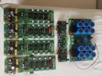
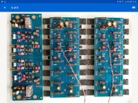
Hi amplitude nice looking build. I notice that you've used the nice looking Russian emitter resistors but they're 0.2R rather than the 0.33R resistors specified in the BOM. Bryston themselves use 0.3R. I wonder if it matters much? I remember that you had problems powering up your amplifier modules - have you made any progress on this front? I'm building two separate stereo amps as I use active crossovers with my loudspeakers. Should make a start on my amplifier modules in the next couple of days.
Hi..
Regarding the emitter resistors, yes they are a little bit lower than specd but I don't think it matters that much, they are pretty accurate and the pcb traces might add a 0.1 ohm on top. I bought a big load of cold war resistors and silver micas, for little money, I hope their parts are as good as their vodka🙂,
The power up as you mentioned is fixed faulty zener. I really like an update when you get modules running, by the way smart idea with your ssr relay as a plugin for regular relay, smart thinking, I might wanna copy your idea if the beast is working satisfactorily
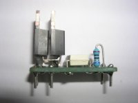
I haven't tested the SSR in a real amp yet but its works fine on the bench switching both ac and dc. The mosfets are FDP083N15A ( 150V, 117A, 6.85 mΩ on resistance ) and the photovoltaic optocoupler is ASSR-V621. Easy, but fiddly, to make on a small piece of perfboard. I'll take some pictures when I make the next one.
Sounds good.. I'll bet they work.. btw what's their current capability?
You stated the current... my bad..
You stated the current... my bad..
Had a look back at the power amp schematic and I notice that lower values of emitter resistors will mean that the output stage current limiting will kick in later than it would with 0.33R emitter resistors. This won't affect the power amp in normal usage but might result in output transistor destruction if its overdriven. Reducing the values of R26-R29 ( currently 300R ) should restore current limiting to the same point as with th 0.33R emitter resistors.
Noted chalky, I didn't think about that when installing the resistors, but anyway the amp will play at max half throttle since my speakers have high sensitivity, but it could maybe give problems when I test its clipping limit, good thing you're observant 🙂, that leads my to the obvious question, how to calculate the value for 0.2 emitters?

Does that mean that you got a bunch of pn100a and pn200a all with the same hfe or did you just match all of the pn100a and pn200a separately. I haven't been through all of my stock but it looks like matching the pnp with the npn transistors might be difficult. Looking at the current limiting I can make the figures work for 300W into an 8R load, but I can't yet see how they manage to get 500W into 4R without the current limiting kicking in. More thought required.
Hi Amplitude, I noticed that you populated the decoupling capacitor positions adjacent to the output transistors; can I ask what value and voltage rating you used? I was going to use 470uf 100V but these seem to be unobtainium. Best I could come up with are Rubycon ZLJ series 330uf 100V. I'm going to use +/-70V supplies by the way.
Hi Amplitude, I noticed that you populated the decoupling capacitor positions adjacent to the output transistors; can I ask what value and voltage rating you used? I was going to use 470uf 100V but these seem to be unobtainium. Best I could come up with are Rubycon ZLJ series 330uf 100V. I'm going to use +/-70V supplies by the way.
Hi.. i had 50 of each pn100/200 I measured all the pn100 and took the highest hfe pair's, I did the same with the 200a and matched the pair's closest, as to the coupling capacitor, I used Cornell dublier 100v 47uf, had a bunch that fitted, my best reason.
The capacitor at the output have a pitch of roughly 5mm, that doesent leave room for big ones,,, maybe use bigger horizontal capacitor, one leg to ground and the other directly to leg of output transistor, fuses are for pussys...🙂
A thought.Hi Amplitude, I noticed that you populated the decoupling capacitor positions adjacent to the output transistors; can I ask what value and voltage rating you used? I was going to use 470uf 100V but these seem to be unobtainium. Best I could come up with are Rubycon ZLJ series 330uf 100V. I'm going to use +/-70V supplies by the way.
The capacitor at the output have a pitch of roughly 5mm, that doesent leave room for big ones,,, maybe use bigger horizontal capacitor, one leg to ground and the other directly to leg of output transistor, fuses are for pussys...🙂
I'll probably go with the Rubicon ZLJs; they're not too expensive. I've got a few 470uf 100v electrolytics with a 5mm spacing, but not enough.
7.5mm spacing seems standard for that size of cap. Bend the leads and support with electronics-friendly silicone?
- Home
- Amplifiers
- Solid State
- Bryston 4B SST clone