I've been pursuing the same idea for quite a while, with limited success. My 2W 6AK6 PP amp includes an L-pad speaker attenuator to help dial down the volume, but as I now know, that is not the best speaker attenuator design, as it has too low an output impedance, which changes the frequency response of the speaker, and therefore, the sound of the amp...Would be nice to hear that powered by a good "fleawatt" poweramp in the living room. Should be cheaper to build with such low power.
I could (and will) put in a better speaker attenuator one day, but I've been increasingly conscious that experimenting for years on end with DIY flea-power valve guitar amps is taking hundreds of hours away from my guitar playing and guitar practice time. In my quest to build a better amp, I'm losing the opportunity to be a better guitarist and musician. The tail is wagging the dog, instead of the other way around!
So just recently I took the plunge, and bought myself a Boss Katana 50. It is the first solid-state guitar amp I have ever owned (in some 35 years of trying) that wasn't immediately disappointing, or worse, outright awful. And it's much more than that - it really is a very good amp, regardless of the technology inside the box.
To my surprise, at apartment-friendly SPL (on the 0.5W setting), with the controls properly set, the Katana 50 can actually sound more "tubey" or "valvey" than my Super Champ XD or '65 Princeton Reverb reissue. And on the 50W setting, I recently performed with my wife in a reasonable sized hall. There was more than enough SPL for that guest appearance gig, keeping in mind no drummer was involved, and the audience was entirely made up of senior citizens.
So the best home guitar practice amp I've found so far isn't one of my flea-powered valve amps, and it certainly isn't either of my Fenders. It's the Katana 50!
The Katana sits in my living room, next to my beater Epiphone solid-body guitar, and both are getting plenty of use. Now I have a chance to re-balance my hobby priorities: work on becoming a better musician first and foremost, and only then tinker with guitar amp building!
The Katana 50 has no speaker output jack to connect to your external speaker cab, but it won't be hard to wire one in - the wires from the internal electronics to the built-in speaker are easily accessible. (Just remember that there's a good chance neither of those wires is grounded: the output may be the H-bridge configuration so common with class-D audio power amp chips these days.)
There are other more expensive members in the Katana line that do have speaker output jacks, by the way.
I should add that it is certainly possible to set the various controls in such a way that the Katana starts to sound crude and solid-state, at least to my ears. But the key thing is that there are also control settings that sound quite convincingly "valvey". (And, of course, there are actual valve amps that sound crude, too!)
-Gnobuddy
Thanks for the link!Octal mojo...I built it for a friend...Maybe 1 watt.
I'm a bit concerned that Jaidn, the OP, never did tell us how he wanted to use his modified amp. We are all guessing that he wants a lot less SPL than the original (nominally 15-watt) amp, but really, none of us knows for sure.
-Gnobuddy
You might find this thread interesting: Rear vent/diffractor cab...my next build in that department are with 4 Norwegian 5 inch fullranges from the 50's
New cab designs don't come along very often. This one looks easy to DIY, and the video suggests that it really does work, providing a much wider sweet-spot.
It is a proprietary design, and about to be patent-protected, so of course you can't make and sell them yourself without proper licensing from the inventor/patent holder. But making a single one for your own personal use is another matter.
I would be tempted to make a test enclosure out of foam-core poster board, which is cheap, light, stiff, and easy to work with. Once you get the dimensions and design figured out, you can, if you want, build a second one out of more durable material. 🙂
-Gnobuddy
I love the Sluckey's 1960 Vox AC-15. I'd like to modify it to fit a single 6V6 power tube (I don't need 15W).
As has been said, going SE from a PP amp is not easy and it will not sound the same at all.
If you just want less power, wire the finals as tridodes. That will about halve the power. Need less, add another RC (or LC) in the power supply to reduce B+ (other stuff will need to change as well (bias for instance).
I have a PP EL84 in triode (and running Class A) that running within its power limits (3.2 W at clipping) is absolutrly fantastic (althou for hifi, not a guitar).
dave
Member
Joined 2009
Paid Member
That was the first thought that crossed my head, but a two-resistor speaker attenuator is considerably simpler.
No doubt the resistors are a simpler option if you don't mind the heat.
For me the attraction of the power scaling is that it doesn't mess around with the original amp too much and as I'm quite comfortable wiring up a single MOSFET on a heatsink it just seemed like the best compromise all said and done (I recently bought some high voltage FETs, plenty of them available from DigiKey). The fact that it scales the plate curves down is why it allows you to hit that distortion at much lower output power because you'll need less signal to swing the operating point along the loadline to reach that knee. Lower power without a lower knee means it stays clean - may as well just turn the volume down in that case.
I see no need to scale the anode voltage. For the output tubes, being Pentodes, the screen grid is a substitute Anode in terms of the curves. And leaving the B+ alone means the operating point for the front end remains unchanged. Now - I'm mostly thinking about the VoX AC4 where most of the distortion tone comes from the output tube and not from the front end so power scaling the output tube is almost ideal. I don't know if that's also the case with the AC15.
AFAIK the London Power scaling started life out using this method, they also put an attenuator before the output tubes grid - a kind of additional vol. control.
Last edited:
The MOSFET in a VVR generates heat, too, you know! 🙂 And much more of it, because valve guitar amps are inefficient, and this means that much more that 15 W has to be drawn from the power supply to put 15 W into the speaker.No doubt the resistors are a simpler option if you don't mind the heat.
In other words, the MOSFET VVR has to dissipate more power than the speaker attenuator does, and it will get hotter than the speaker attenuator, all else being the same! 😀
I'll try and show you why there is, in fact, a need to scale the anode voltage. To do this, I created the three attached images. Take a look at these, and I will walk you through how they clearly show the problem with NOT scaling the anode voltage.I see no need to scale the anode voltage.
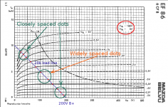
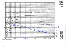
I couldn't quickly find a big pentode datasheet showing curves for multiple screen grid voltages, so I just used an EF86 data sheet (this one: https://frank.pocnet.net/sheets/020/e/EF86.pdf ). Exactly the same thing happens with bigger pentodes as well, so the conclusions we draw from the EF86 data apply equally well to bigger pentodes like EL84s and EL34s and so on.
The first image shows a load-line for 200 volts anode voltage, and a 20k anode load. The screen grid voltage is 180 volts (circled in red.)
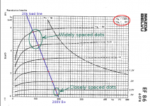
The second image shows the SAME 20k load-line, with the SAME 200 volts anode voltage. However, screen voltage has been lowered to 100 volts, pushing all the curves down, as you said.
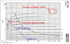
The third image is the same as the second image, except I have compressed the vertical scale to match the first image. This lets you see that the curves have been squashed down, but the 20k load-line is the same as it was before. (This follows simply from Ohm's Law: notice that the load-line goes through the two points (Ia = 0, Va = 200V), and (Ia = 10 mA, Va = 100V) in EVERY one of the three images.
One, and only one, unique straight line can be drawn through the same two given points. Therefore this shows you that the load-line is exactly the same line in every case. It only appears different in the middle image because the manufacturers plotted the 100V curves using a different (expanded) vertical scale to account for the smaller anode currents.
So what's the problem with not scaling anode voltage along with screen voltage? The problem is that the anode curves got pushed down, but the load line did not - so the load line is now much higher above the knee of the curves (in the second and third images, with Vg2 = 100V), and this drastically changes the distortion characteristics.
To make it clear to you why the distortion characteristics change, I plotted the red dots you see on the images.
There is a dot at each point where the load-line crosses an anode curve, so the position of each dot tells you the anode current and voltage at that value of incoming signal voltage (the voltage on the control grid corresponding to that particular anode curve.) The crucial thing to understand is that, if the pattern of spacing between the red dots changes, so does the sound of the distortion produced by the amplifier.
As you can clearly see by comparing the images, the pattern of these red dots is very different for the first image (Vg2 = 180V), and the second and third images (Vg2 = 100V).
At a screen voltage of 180V and anode voltage of 200V, both ends of the output signal are compressed (red dots are closer together), while the middle of the waveform is expanded (red dots further apart.)
At a screen voltage of 100V with the same 200V anode voltage, the bottom end of the output waveform is compressed (red dots closer), but the top end is expanded (dots further apart.) The type of distortion is quite different, the distortion spectrum is different, and so these two cases will sound different to the human ear.
So we conclude that the amplifier will not sound the same, because we lowered only the screen voltage, and failed to lower the anode voltage by the proper amount at the same time. Lowering the screen grid voltage - without lowering the anode voltage to match - caused a drastic change in distortion characteristics.
We do not want this from a good voltage scaling system - we would like the distortion characteristics to stay the same, with only the output power being reduced. In other words, we want the load-line to move with the knee of the curves as the voltage is scaled down. And this is only possible if you scale both screen and anode voltages together, and by carefully calculated, but different, amounts.
-Gnobuddy
Attachments

Member
Joined 2009
Paid Member
The MOSFET is dissipating heat of course, but only the current drawn by the screen grid flows through it, which is on average 20% of the anode current. I figure this is going to be much cooler thank hanging a resistive load off the amplifier to burn off the excess watts. And if the screen grid current is lower because the curves are squashed down, the MOSFET will run cooler than it would when the amp is running with non-squashed plate curves.
Last edited:
Member
Joined 2009
Paid Member
Yes, the load-line gradient is fixed by the load impedance. However, it does not cross the axes at fixed points like you show, it always intersects the point corresponding to the grid bias used and anode voltage. As the curves squash down the idle current reduces.
Look at your first plot. At 100V and zero bias you'd have 11.5mA. Now look at the 2nd plot and at 100V and zero bias you'd have only 5.7mA. So the idle current moves down as the curves are squashed. Therefore, the load line moves down too, but keeping it's gradient the same. It's perhaps not quite so simple since the bias voltage will depend on the biassing scheme used too.
Look at your first plot. At 100V and zero bias you'd have 11.5mA. Now look at the 2nd plot and at 100V and zero bias you'd have only 5.7mA. So the idle current moves down as the curves are squashed. Therefore, the load line moves down too, but keeping it's gradient the same. It's perhaps not quite so simple since the bias voltage will depend on the biassing scheme used too.
Last edited:
You're quite right, I forgot that you were not planning to run the anode currents through the MOSFETS.The MOSFET is dissipating heat of course, but only the current drawn by the screen grid
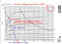
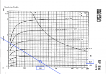
And here are two images showing why your really should run the anode current through a (second) MOSFET. 😀
For an EF86, by lowering anode voltage from 200V to 120V at the same time screen voltage is lowered from 180V to 100V, the load-line shifts in such a way that it stays in roughly the same place relative to the new "knee" of the curves.
Note that the slope of the load-line is the same in both cases (20k, or 1 mA for every 20 V). But by lowering B+, we slide the line to the left at the same time as we are lowering the screen voltage. If we slide it the correct amount to the left, the y-intercept will end up in the correct place, below the knee of the new, lower screen voltage curves.
-Gnobuddy
Attachments
Member
Joined 2009
Paid Member
The simplest case, fixed bias. Let's fix the bias at -2.5V and the Anode voltage at 200V. I picked a load line of 500/6 = 83k for my convenience.
The loadline in both graphs has to pass through -2.5V and 200V. See how at reduced screen grid voltage the idle current drops. See how the load line kinda clips through the knee in a similar way in both cases.
In more detail. At g2=180V the idle current is 5mA. And we get into serious compression when the grid voltage swings 2V positive from idle to -0.5V at which point the anode current swings up to 7mA, a change of 2mA.
At g2=100V the idle current is now only 1.5mA and we get into serious compression when the grid swings 2V positive at which point the anode current swings up to nearly 3mA, a change of 1.5mA. This is a smaller change in current through the OPT than we see at the higher g2 voltage meaning the power output is lower but we still enjoy similar distortion.
Attachments
Last edited:
To keep things simple, I'm plotting resistive load lines. For these, what you said above is incorrect - the load line is determined entirely by the B+ voltage and load impedance, and not by the operating point.Yes, the load-line gradient is fixed by the load impedance. However, it does not cross the axes at fixed points like you show
This is easy to demonstrate: if there is zero anode current, there is no voltage drop in the anode load, therefore the anode is at full B+ voltage. That marks one end of the loadline, at the point (anode current = zero, anode voltage = B+).
To find the other end of the load line, imagine the anode voltage is zero. This puts the full B+ voltage across the anode load resistor, and Ohm's law says the current through it is (B+/Ra). This fixes the other end of the load-line, at the point (anode current = B+/Ra, anode voltage = zero.)
You can change the screen and control grid voltages, and they will move the anode curves around. But that won't move the load-line; it cannot, because doing so would violate Ohm's law. You can only move the load-line by changing B+.
Now let's consider the case where the anode load is a transformer primary, so that there is no DC voltage drop across it, and quiescent anode voltage = B+. This time I agree that yes, the entire load-line will now slide up and down with quiescent current. But in general the quiescent current isn't directly proportional to the screen grid voltage, so I'm not convinced that the load-line will move just the right amount to preserve the relationship between the load-line and the knee of the curves. And if it does, the other end of the load-line will move on the voltage axis, to the left; this means the output valves have moved away from class AB and towards class B, which presumably, will also change the tone of the amp.
I've read that Kevin O'Connor also included scaling for the bias voltage on the control grids, along with scaling B+ and screen grid voltage. Presumably he found that you have to scale all three if you want to keep the right relationship between load line and anode curves and operating point with a transformer as anode load.
For now, I can't think of a reasonable way to prove this one way or the other using just manufacturer data sheets, so I'll have to drop the discussion here. Not to mention, I have to go finish cooking dinner now!
-Gnobuddy
Member
Joined 2009
Paid Member
I think you’re right you may end up having to scale the bias voltage if it’s not fixed, to get the most benefit of a simple power scaling scheme, but it would be interesting to try the simple experiment on just the screen grid and I had a project to do that with a clone of the AC4 but it is sitting on the shelf ...
Last edited:
Sorry about the overlapping posts, you posted while I was composing my reply to your earlier post.The simplest case, fixed bias. Let's fix the bias at -2.5V and the Anode voltage at 200V.
Thanks for the graphs in your most recent post. Interestingly, your graphs show exactly what I was concerned about in my last post - the operating point shifting towards class B if you lower screen voltage without a corresponding reduction in B+.
In your first graph, the stage is operating in pure class A; in fact, there is still anode current flowing when the anode voltage hits twice B+, or 400 volts. DEEP into class A.
In the second graph, the output stage cuts off when the anode voltage reaches 250 volts, much less than the eventual 400V peak. This time it's operating nearly in class B.
Surely that shift alone causes drastic change in tone?
From your two images, it also looks to me as if the load line has now moved further below the "knee" as the screen voltage was reduced; the opposite problem to what happens with a resistive anode load!
And now I really must go cook dinner, or we'll go to bed hungry tonight!
-Gnobuddy
I agree, and if you ever do the experiment, I hope you'll share the results here on diyAudio!...it would be interesting to try the simple experiment on just the screen grid...
Meantime, the chicken is well on its way to being cooked, and I've chopped the onion and all the veggies, so I have a few minutes free to catch up on the mysteries of power scaling. 🙂
-Gnobuddy
I expect it would work fine in that service; you'd probably need a pot or a Herzog box to bring it down to line levels.One of the things I never did was explore how it worked as a Herzog, though that had been part of the original intention.
The milliamp design was a response to an AX84 challenge to design a current-production, single tube amp suitable for beginners to dabble with at low cost, hence the 12DW7. I did not have a handy SE output transformer and decided to try the parafeed output arrangement. That actually worked better than I expected. I would have preferred a pentode in the preamp for the gain, but nothing suitable (such as the 6CU8) was still in current production at the time I was doing this. It's still on my list of things to play with some day.
Stph
Member
Joined 2009
Paid Member
This time it's operating nearly in class B.
Surely that shift alone causes drastic change in tone?
Thankfully it's not as abrupt as that - as it approaches Class B the OPT reflects a higher load impedance to the tube cutting-off and extends the cut-off region.... smooths things out in a very vague fashion. I've no idea what it means for the sound though as other stuff starts happening such as bias shift and changes in current draw on B+. Nevertheless, the simplicity of a MOSFET source follower on the screen grid appeals to me greatly. At the very least, it'll more or less eliminate the screen supply as a culprit of hum and more importantly, it'll give you another knob to twiddle on your amp 😀
Last edited:
Yeah, it would need some 20 dB attenuation to bring it down to 100 mV or so for guitar-level inputs.I expect it would work fine in that service; you'd probably need a pot or a Herzog box to bring it down to line levels.
Things get silly at such low output power. It only takes 1.27 volts RMS to supply 200 mW to an 8 ohm load. That's about +1 dBv or +2 dBu - not too far from pro-audio line level, with no attenuation at all!
I found an interview with Randy Bachman in which he said that at first the Herzog was used with a Fender guitar amp, but this didn't quite nail the smooth, singing, sustain he was looking for. Gar Gillies then built a guitar amp for Bachman, to go with the Herzog he'd also built for him. Apparently it was the combination of these two - Herzog and custom guitar amp - that finally produced the sound Bachman had been searching for.
We all know Champs can be harsh little beasts when overdriven, and I've always wondered why Bachman's sound was so mellow, as his Herzog was really nothing more than a Champ. So now we know - the custom guitar amp Gar built was part of the reason.
I haven't been able to find any further information, and I'm curious what tricks Gar played with his amp design. Was it just a matter of heavy treble filtering? Or did he use more gain stages than usual, with resistive attenuators in between, to generate more of that smooth, singing distortion?
How well did you like the result?The milliamp design was a response to an AX84 challenge to design a current-production, single tube amp suitable for beginners
I've been disenchanted with the single-tube guitar amp designs I've tried. There was never enough gain, and with only two vacuum devices in the signal chain, there isn't much "tubeyness" to the sound, either.
As a result, I've been converted to the belief that the signal has to go through quite a few slightly-distorting tube stages even to get a convincingly "tubey" clean tone, never mind a rich overdriven tone. Even in something simple like a Princeton Reverb the signal goes through no fewer than four slightly nonlinear active devices (I didn't count the cathodyne stage, which has so much local negative feedback that it's too linear to matter for guitar sound.)
-Gnobuddy
I agree, it's appealing simple. I hope you try it out and tell us how well it works. 🙂Nevertheless, the simplicity of a MOSFET source follower on the screen grid appeals to me greatly.
I experimented with the even simpler idea of using bigger-than-usual screen resistors in my little 6AK6 amp, and wasn't enchanted with the results. The amp became cleaner at low output power levels, and when clipping did arrive, it arrived more abruptly. I probably should have anticipated that, since bigger screen resistors are actually a form of local negative feedback!
You've piqued my curiosity about power scaling in general now, and I'm starting to wonder what it would take to implement the whole enchilada - being able to scale screen voltage, anode voltage, and control grid (bias) voltage, all with the twist of one knob, with trimpots to set their relative rates and initial voltages. Hmm.
-Gnobuddy
Member
Joined 2009
Paid Member
You've piqued my curiosity about power scaling in general now, and I'm starting to wonder what it would take to implement the whole enchilada - being able to scale screen voltage, anode voltage, and control grid (bias) voltage, all with the twist of one knob, with trimpots to set their relative rates and initial voltages. Hmm.
I suspect the trick set-up would be to have all the biases relate to B+, then just scale B+ and the rest will follow.
As a beginner electronics project it was fine, but as noted in my web page I would not recommend it as a guitar amplifier. It might be okay with a 6CU8 pentode preamp/triode power amp, but I haven't made time to try that out yet. The parafeed output provides an extra filter stage by means of the transformer coupling cap, so it does afford some treble smoothing. With just the single triode in the preamp, though, it simply doesn't have the oomph to overdrive the output triode suitably.How well did you like the result?
I would agree. One thought I had about the milliamp design was to put an LND150 in front as a boost circuit. I think that would probably work reasonably well to get the drive levels into the power amp up to reasonable levels. I'm not sure what it would do to the tone though.I've been disenchanted with the single-tube guitar amp designs I've tried. There was never enough gain, and with only two vacuum devices in the signal chain, there isn't much "tubeyness" to the sound, either.
As a result, I've been converted to the belief that the signal has to go through quite a few slightly-distorting tube stages even to get a convincingly "tubey" clean tone, never mind a rich overdriven tone.
Stph
- Status
- Not open for further replies.
- Home
- Live Sound
- Instruments and Amps
- Vox AC15 EF86 with one power tube