There are many ways to skin a cat. I have zero experience of designing passive xos, but the freedom of choices that dsp gives is just fantastic. And you can easily create several layouts and listen to them - a wonderful playground for us little boys with propeller-hats!
First study the "natural respionse of each driver in baffle/box, also off-axis. Then eq the low end roll-off, baffle step and cone resonance peaks. Check the low-end distortion of eq'd drivers too!
By previous, you have and idea of where and what order xo you can set, to get good phase match with even order symmetrix xo or anything special that you like. With 3-4 ways you can use LR2 which sounds superior to LR4 to my ears. Mid-tweet xo is usually the most challenging. Make 2-3 alternative versions and listen!
A 2-way is always a bad compromise and in my opinion total waste of diy-time.
A 2-way is always a bad compromise and in my opinion total waste of diy-time.
Note: there is a thread for that sentiment!
Warning RANT ahead: I totally agree, yet this is what many of the passive crossover DIY loudspeaker builders are making. Sometimes the DIY meet is full of them, although it's not nearly as bad as a small fullranger in a horn! Nearby me (now) there are a number of good loudspeaker DIY folks, and to make it interesting they impose some kind of "twist" (usually a limitation of some kind) and then have a competition. This has been things like "use only 5 of fewer crossover components" or "your design must include driver X". Fine, I guess if that sparks some interest and creativity.
Heck, I own and listen to (on a daily basis) an awesome pair of not expensive 2-way loudspeakers: the powered JBL 306P mkII. I think the sound is fantastic above 100Hz (it's augmented by a DIY sub below 100Hz) and they cost me a mere $160 each, delivered. Why in the world would I DIY a small 2-way when I can purchase a speaker like this? It has its limitations in SPL and so on, but within its comfort zone this is IMHO an amazing speaker for the price. Instead, save your DIY loudspeaker efforts for something that is a little more special than a boxed 2-way...
I feel that using active systems with DSP releases you from so many constraints related to loudspeaker building you are free to explore questions like "what kind of loudspeaker (response) might sound best" and build loudspeakers that you just cannot buy because they are impractical or not cost effective for a business to build, distribute, and sell, or that you just could not afford otherwise (without building them yourself).
You never owned an analogue equaliser?you are free to explore questions like "what kind of loudspeaker (response) might sound best"
You never owned an analogue equaliser?
An EQ/PEQ only changes the input power vs frequency. It cannot change the radiation pattern of the loudspeaker itself, or correct certain other response problems.
Once you build a flawed speaker you cannot "un-flaw" it using EQ.
Why would you want to do that?It cannot change the radiation pattern
Why would you want to do that?
Because not all radiation patterns "sound" the same. They are an inherent property of the type of drivers chosen, and the type of loading they are put in. There is a mighty big difference in the radiation patterns of boxes, horns, and open-back or free-air loading... but the differences cannot be changed by changing the input signal in terms of phase and amplitude (e.g. by EQ or filtering).
The radiation pattern is fixed early on in the design process and you are stuck with it there and afterwards.
Choose wisely.
I put much into designing the wanted directivity. I won't use a horn randomly. I will even invent my own horn. But I don't need to change it later because it is already correct.
Well this is as far as I've got with measurements
IMAGES
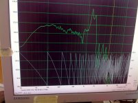
Woofer24smooth is nearfield Woofer only, rest muted
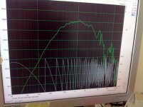
Mid24smooth is nearfield Mid range only, rest muted
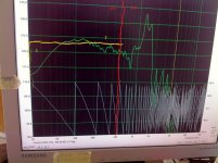
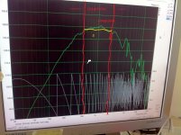
Focusrite19-5-19 etc is farfield with all drivers unmuted with LR4 crossovers at 500Hz and 2KHz (I did not want to measure Tweeter without protective Highpass) Reliable ? above 300Hz
These were taken with Dayton EMM6, Focusrite Solo and ARTA. Would it have been better to have used HFD (Hypex?)
What's next?
IMAGES
Woofer24smooth is nearfield Woofer only, rest muted
Mid24smooth is nearfield Mid range only, rest muted
Focusrite19-5-19 etc is farfield with all drivers unmuted with LR4 crossovers at 500Hz and 2KHz (I did not want to measure Tweeter without protective Highpass) Reliable ? above 300Hz
These were taken with Dayton EMM6, Focusrite Solo and ARTA. Would it have been better to have used HFD (Hypex?)
What's next?
Attachments

Forgot to mention. On Focusrite 19-5-19 Woofer channel gain 10dB, Mid channel Gain 2.5dB and tweeter 0. This was an estimate after previous trial measurements.
You can set target response curves with ARTA in the overlay menu.
For example, if you want 500Hz and 2kHz LR4 response for the mid, you can set the target and compare your response to the target, nearfield is for woofer only.
For example, if you want 500Hz and 2kHz LR4 response for the mid, you can set the target and compare your response to the target, nearfield is for woofer only.
The measurements of the drivers (each operating alone) look fine.
The measurement of the "system" has some problems:

The main problem with this measurement is that the resolution is too poor (300Hz or so) to really make out much of anything below 500Hz. In fact, you should ignore all the data below about 500Hz - it has nothing to do with reality and is in fact WRONG, despite the fact that your measuring program spits out some numbers for these frequencies. I explained this before.
Around 500Hz I would make a GUESS that the woofer and midrange are out of phase, and that the woofer level is too high, but the confidence I can assign to that is *maybe*.
I would try to reverse the phase of the woofer, drop the level by about 5dB, and take another "system" measurement. When you do that, use the same mic position that you used so far for the system measurement to do a measurement. Then try to place the mic on the floor (tip of mic touching the floor) at least 1.5m away and take another measurement. This will remove the "floor bounce" from the measurement, but you will be off axis. See if you can use a longer gated window with the floor measurement.
If you cannot get any better resolution on the "system" measurement there are some other ways to try and get better info but they are much more complicated and will involve a modeling program.
The measurement of the "system" has some problems:
The main problem with this measurement is that the resolution is too poor (300Hz or so) to really make out much of anything below 500Hz. In fact, you should ignore all the data below about 500Hz - it has nothing to do with reality and is in fact WRONG, despite the fact that your measuring program spits out some numbers for these frequencies. I explained this before.
Around 500Hz I would make a GUESS that the woofer and midrange are out of phase, and that the woofer level is too high, but the confidence I can assign to that is *maybe*.
I would try to reverse the phase of the woofer, drop the level by about 5dB, and take another "system" measurement. When you do that, use the same mic position that you used so far for the system measurement to do a measurement. Then try to place the mic on the floor (tip of mic touching the floor) at least 1.5m away and take another measurement. This will remove the "floor bounce" from the measurement, but you will be off axis. See if you can use a longer gated window with the floor measurement.
If you cannot get any better resolution on the "system" measurement there are some other ways to try and get better info but they are much more complicated and will involve a modeling program.
Hi
I agree with wht you say about this "system" measurement, but I was only going to use it as tweeter measurement above 2KHz.
I also thought polarity should be changed between Woofer and Mid (because of the dip) although I was super careful with the wiring to get all the negs, negs and pos, pos.
I agree with wht you say about this "system" measurement, but I was only going to use it as tweeter measurement above 2KHz.
I also thought polarity should be changed between Woofer and Mid (because of the dip) although I was super careful with the wiring to get all the negs, negs and pos, pos.
Hi
I agree with wht you say about this "system" measurement, but I was only going to use it as tweeter measurement above 2KHz.
I also thought polarity should be changed between Woofer and Mid (because of the dip) although I was super careful with the wiring to get all the negs, negs and pos, pos.
If you just flip the polarity of one driver in blind, it's possible to create an even larger dip in the response. First, one need to identify what causes the dip.
For example if the mid-driver have a natural 2nd order roll-off as we can see from the measurements, then a 4th order high-pass is applied, we get a 6th order roll-off. And if the woofer has a proper 4th order roll-off with the low-pass applied, then you have a roll-off mismatch and a dip in the response with good chance and no polarity flip can repair this problem.
That's why I suggest beginners to fatten the response first and then use the desired filter if we talking about a DSP based crossover. So that way you can be sure that the acoustical curves will follow tha applied crossover topology and you can easily experiment with other crossover frequencies and curves in the future.
Last edited:
ATC uses a 4th order roll-off around 380Hz with their dome mid because this driver is strongly excursion limited in the low-end. So i don't suggest any lower crossover than this.
So don't overdo the response flattening to 20Hz. One octave from the crossover point is usually enough.
So don't overdo the response flattening to 20Hz. One octave from the crossover point is usually enough.
I will try the reverse polarity first to see what happens. 500hz crossover is in the middle of the overlap of woofer and mid. The woofer (without xover) slopes down well above 500 and Mid (without xover) slopes down well below the 500
i would appreciate suggestions as to what filters to use (in Hypex Filter Designer) to flatten the freq response.
Image of Woofer24smoothLR4LR4: In this nearfield measurement, no xover is applied (although it is marked as red vertical line) and other drivers are muted.
Zone 1, how flatten from approx 60Hz to 20Hz?
Use Shelf or Asym Shelf and how apply/configure?
Zone 2 worth flattening?
Image of Mid24smoothLR4: This is nearfield midrange, rest muted. No crossovers applied though bandpass marked in red @ 500Hz & 2KHz.
Zone 3 worth flattening?
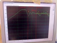
Image of Farfield: Farfield of course. Reliable down to 300Hz? No speaker muted. LR4 crossovers applied @ 500Hz & 2KHz.
Mainly for tweeter assessment.
Zone 5 from 10K or 12K, can this be levelled? What filter use?
Zone 4 I presume Boost/Cut @ approx 3.5KHz but don't know what Q?
Zone 6, Dip between Mid and Woofer. CharlieL suggests change woofer polarity as could be out of phase and freqs cancelled. If polarity change fixes dip, fine. If dip increases it's something else. Could be natural down slope of both drivers at xover freq. Deniberi recommended flattening responses before applying xovers. CharlieL suggests reducing the gain on the woofer. I will do that when I have applied all the other filters.
If I master that lot, will deal with PHASE.
Image of Woofer24smoothLR4LR4: In this nearfield measurement, no xover is applied (although it is marked as red vertical line) and other drivers are muted.
Zone 1, how flatten from approx 60Hz to 20Hz?
Use Shelf or Asym Shelf and how apply/configure?
Zone 2 worth flattening?
Image of Mid24smoothLR4: This is nearfield midrange, rest muted. No crossovers applied though bandpass marked in red @ 500Hz & 2KHz.
Zone 3 worth flattening?
Image of Farfield: Farfield of course. Reliable down to 300Hz? No speaker muted. LR4 crossovers applied @ 500Hz & 2KHz.
Mainly for tweeter assessment.
Zone 5 from 10K or 12K, can this be levelled? What filter use?
Zone 4 I presume Boost/Cut @ approx 3.5KHz but don't know what Q?
Zone 6, Dip between Mid and Woofer. CharlieL suggests change woofer polarity as could be out of phase and freqs cancelled. If polarity change fixes dip, fine. If dip increases it's something else. Could be natural down slope of both drivers at xover freq. Deniberi recommended flattening responses before applying xovers. CharlieL suggests reducing the gain on the woofer. I will do that when I have applied all the other filters.
If I master that lot, will deal with PHASE.
Attachments
Ok, i suggested the response flattening but something may not clear.
1. Leave the woofer's low-end response alone until you measure the farfield response at the listening spot.
2. The flattening is important in the pass-band and at least 1 octave below and above from the crossover points for LR4 slopes.
3. What Q you need is dictated by the driver response anomalies. Q is the working frequency width of a filter. You need experiment here, try different Q-s for best response. For example: a sharp change in the driver response needs a higher Q filter to counteract.
Last edited:
Ok, i suggested the response flattening but something may not clear.
1. Leave the woofer's low-end response alone until you measure the farfield response at the listening spot.
He can't do that. The speakers have been built into a wall and the room is not large. The farfield response is contaminated by reflections off of room surfaces below about 350-500Hz, and that is also the resolution for the rest of the audio spectrum for any far-field measurements.
The only solution is to use a near-field measurement on the woofer and assume that, because the speaker is built into the wall, there is no baffle step. At least I feel that would be a good first order approximation that one could make in this situation.
I mean non-gated farfield response. How you want to tame room modes with a gated response?He can't do that. The speakers have been built into a wall and the room is not large. The farfield response is contaminated by reflections off of room surfaces below about 350-500Hz, and that is also the resolution for the rest of the audio spectrum for any far-field measurements.
The only solution is to use a near-field measurement on the woofer and assume that, because the speaker is built into the wall, there is no baffle step. At least I feel that would be a good first order approximation that one could make in this situation.
- Home
- Loudspeakers
- Multi-Way
- Freq measurements and Hypex Filter Design adjustments