i would go for a dual mono if you'r chassis allows it. Mine don't. i need too fit 5ch inn to one chassis.
Hi, I'm new here. I have purchased the parts and boards for this amp. I was wondering if I would have a problem remote mounting the power transistors. In my chassis the heat sinks are in the middle and I don't think I can fit the boards on the heat sinks. I was thinking 18 Gage and heat shrink the Leeds on the transistors.
If you can't fit the boards on the heatsinks, than the heatsinks are too smal.
Unless it's fan cooling.
Unless it's fan cooling.
I'll take care of that. Are there issues with connecting the power transistors with 3-4 inch Leeds?If you can't fit the boards on the heatsinks, than the heatsinks are too smal.
Unless it's fan cooling.
Yes, having the output transistors on leads like that significantly increases the risk of oscillation. Moving the output transistor base resistors from the board to the end of the lead can sometimes help if this is what you need to do.I'll take care of that. Are there issues with connecting the power transistors with 3-4 inch Leeds?
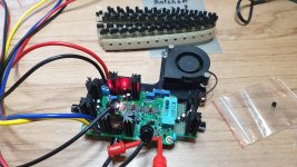
Hi Chris. Just using my transistor matcher. Not sure why the other image did not upload.
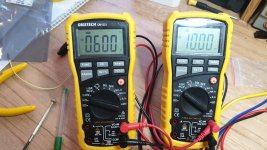
The meter on the left is measuring the VE (voltage at the emitter) the other meter is measuring the IE current through the emitter. Just need to times the meter reading by 10 as im using a 10ohm sense resistor. So 10mv corresponds to 1mA.
The meter on the left is measuring the VE (voltage at the emitter) the other meter is measuring the IE current through the emitter. Just need to times the meter reading by 10 as im using a 10ohm sense resistor. So 10mv corresponds to 1mA.

Last edited:
Nice work you're a legend! ThxHi Chris. Just using my transistor matcher. Not sure why the other image did not upload.
The meter on the left is measuring the VE (voltage at the emitter) the other meter is measuring the IE current through the emitter. Just need to times the meter reading by 10 as im using a 10ohm sense resistor. So 10mv corresponds to 1mA. View attachment 765877
Hi Stuart,
Although your matching device looks very complicated (there is a lot going on there), it doesn't appear to run a pair at the exact same temperature. So it would be a good pre-sort for the final match jig that would be based on a long tailed pair with those transistors mounted together (touching) and isolated from outside air and air currents.
Can you share any additional information on your matching jig?
-Chris
Hi Stuart,
As your transformer is potted, is there really a concern about mounting it with a metal bolt?
As your transformer is potted, is there really a concern about mounting it with a metal bolt?
Hi Stuart,
As your transformer is potted, is there really a concern about mounting it with a metal bolt?
Very much so. All toroidals have to be mounted without creating a shorted turn, and being potted or not has no bearing on this as magnetic fields pay no attention to potting compound!
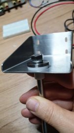
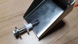
No sure what potted means. But I can assure you that I do no have a shorted turn. The bolt iscompletely isolated from the top mount😎]
I thought the concern was to ensure you did not connect the top and bottom of the case with a steel bolt travelling through the center of the donut.
I thought the concern was to ensure you did not connect the top and bottom of the case with a steel bolt travelling through the center of the donut.
that is the concirn. but pottet or not, it's all the same. it's got nothing to do With the transformer. it's all about the Connection between the topend and the bottomend of the bolt going thrue the transformer.
I thought as long as one end is grounded it's fine but you do not want to create a loop where both go back to the chassis. Ive heard it has to have one end grounded as it could act like a secondary and if not then you could cop a belt if you touch it. But ideally it's better to have a nylon bolt. I'm no expert though. I've heard it's better for interference noise to run with a nylon.
- Home
- Amplifiers
- Solid State
- diyAB Amp The "Honey Badger" build thread


