I am not entire clear about what you mean by "not directly in the signal path." Considering the amp in the simplified picture of an opamp. The opamp has not just one, but two input signals. One input signal is the signal to be amplified, and the second input is the feedback signal. The feedback current, which is the thing that generates the feedback signal, flows through the voltage divider formed by the feedback resistor and the resistor to ground (through the DC blocking cap), and "directly" through the DC blocking cap to ground, and the feedback voltage signal is sampled as the output of the voltage divider. So, to me, the DC-blocking capacitor is "directly" in the path of the feedback current and directly affects the feedback signal. I am not trying to play a game of semantics, but this seems to me to mean that the cap is directly in the signal path of the feedback signal. Is there something wrong with this view?
I'm unaware of your schooling regarding electronics, but I will say that I'm a retired (after 45 years) long-time audio/video service technician, professionally educated, and of course understand the workings regarding amplifiers.
In "feedback" portions of amplifiers, its levels are substantially below the input signal - a fraction in fact. It's a signal "sent back" to correct and control the operation of the amplifier, as well as the speaker attached to it. Amplifier "damping factor" is one reason for providing feedback.
Being "way below" the main signal, and not directly in the main signal path, it's critical nature that you seem to worry about is hardly a concern.
So now there's a "main signal path", and presumably a "non-main signal path"? And the electrons know which way to turn?
Are the input signal and the feedback signal not close to being identical? Except that the feedback signal is working up to 1-5 MHz.
Are the input signal and the feedback signal not close to being identical? Except that the feedback signal is working up to 1-5 MHz.
The feedback signal, while being much lower in level, is also opposite - out of phase - with the main original signal, and used to correct "to a point" any nonlinearities of the amp, as well as reducing distortion.
There is extensive and more complete information regarding this subject if you look around on the internet for it.
Feedback lines are a fractional part of the audio chain, and not directly in the signal path.😱
That stated, I see no sense fussing and obsessing over what type and quality level is important.
What are you talking about?
They are VERY MUCH in the signal path.
In fact NFB ***corrects*** signal through amplifier.
To be even more precise, amplifier does not actually amplify input signal 😱, but the difference between input signal and a sample from the output signal.
Guess how we get that sample and what network does it go through?
An important part of which is ... ummmm .... that electrolytic cap.
Still think it´s not in the signal path?
EDIT
Sorry but you are wrong.the importance of this capacitor in a solid state amp is 0. Makes no difference at all audible or measurable.
It does all the difference a capacitor can make when straight in the signal path: see above.
Any distortion, phase shift, nonlinearity, anything you can detect or measure across it will be directly injected to the - input of the amplifier.
Even more, amplifier will *try* to faithfully follow signal dropped across that very capacitor and the resistor to ground, go figure.
EDIT 2:
I never bring this up out of courtesy but since you mention it, being an audio video service technician does not mean by itself a high theoretical level of understanding.I'm unaware of your schooling regarding electronics, but I will say that I'm a retired (after 45 years) long-time audio/video service technician, professionally educated, and of course understand the workings regarding amplifiers.
Some people speak of the "Internet University" education.There is extensive and more complete information regarding this subject if you look around on the internet for it.
That is a mixed bag, there is some useful data, lots of iffy or wrong type, it´s often hard to tell one from the other, not exactly the best education out there.
The MAIN problem is that it can not go very deep, so information tends to be superficial, and many times anecdotic.
NO NO NO NO NO: NFB signal is "practically" exact same level as input signal; amplifier uses the minute difference between them.In "feedback" portions of amplifiers, its levels are substantially below the input signal - a fraction in fact.
The principle behind NFB lies precisely upon the amplifier trying to make that difference exact ZERO, go figure.
True, but this added to your earlier statements proves you have a superficial knowledge about how NFB works.It's a signal "sent back" to correct and control the operation of the amplifier, as well as the speaker attached to it.
Amplifier "damping factor" is one reason for providing feedback.
Not really WRONG, there´s some shreds of truth in it, but still showing misunderstanding so you don´t realize some basic errors.
Again, not way below at all.Being "way below" the main signal, and not directly in the main signal path, it's critical nature that you seem to worry about is hardly a concern.
Last edited:

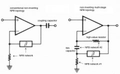
Although multi-stage feedback topologies are typically associated with inverting applications, the following non-inverting variation can be useful for attenuating DC without the use of high capacitance values (IOW electrolytics) or DC servos.
In the right figure, the addition of NFB network #2 with its high resistance value (hundreds of kohms, or megaohms) allows the capacitance value to be reduced to a range where film capacitors will be practical.
Apologies for the small text size - hope that blowing up the drawing will make it readable!
hth, jonathan
Attachments
Hello,
For a current to circulate in an electronic circuit, it should find a closed path.
How circulates a current in an audio output stage ??
Throught the power transistors, the loudspeaker and ... ?
And, the reservoir capacitors, which also are part of the power supply .
And, the output power transistors don't work in A class, with a current source, but in AB class !
The drawing comes from here: Power Supply Resevoir Size
Discussion N° 372.
It's a long discussion !
HTML:
The supply rails are not the signal path, a constant current source is not the signal path (but a current mirror might be)For a current to circulate in an electronic circuit, it should find a closed path.
How circulates a current in an audio output stage ??
Throught the power transistors, the loudspeaker and ... ?
And, the reservoir capacitors, which also are part of the power supply .
And, the output power transistors don't work in A class, with a current source, but in AB class !
The drawing comes from here: Power Supply Resevoir Size
Discussion N° 372.
It's a long discussion !
Attachments
I'm not disputing that, I'm disputing that the rails are on the signal path. A signal is _information_, not electrons. And in a voltage amplifier the information is in the voltage and not the current.
I have a simulated amp at the moment - I can inject 1V on the rails and it will influence the output to the tune of less than a microvolt - 120dB rejection, the rails are not on the signal path. Any component capacitively coupling to the input node would have more influence on the output, without even being connected. The air around the input node has more right to be considered signal path than the supply rails!
I have a simulated amp at the moment - I can inject 1V on the rails and it will influence the output to the tune of less than a microvolt - 120dB rejection, the rails are not on the signal path. Any component capacitively coupling to the input node would have more influence on the output, without even being connected. The air around the input node has more right to be considered signal path than the supply rails!
On the contrary, in a typical SS amp the feedback network is 'in the signal path' more than the forward gain part of the circuit.wiseoldtech said:Feedback lines are a fractional part of the audio chain, and not directly in the signal path.
I'm not sure if this is a well-disguised attempt at humour.gabdx said:the importance of this capacitor in a solid state amp is 0. Makes no difference at all audible or measurable.
Anything shunting the signal path is in the signal path, including CCS. Unfortunately, the concept of signal path is misleading, especially to those who use the term a lot.Mark Tillotson said:The supply rails are not the signal path, a constant current source is not the signal path (but a current mirror might be).
As others have said, a big enough electrolytic will drop the signal voltage to negligible levels so the distortion will be smaller than negligible. A bypass cap will probably do nothing; if you are unlucky it will resonate so omit it unless you are aiming to sell the amplifier to people who don't understand electronics.
No. In most SS amps the feedback signal is about the same amplitude as the input signal, and it is more in the signal path than the main gain circuit.wiseoldtech said:In "feedback" portions of amplifiers, its levels are substantially below the input signal - a fraction in fact.
It's a signal "sent back" to correct and control the operation of the amplifier, as well as the speaker attached to it.
Amplifier "damping factor" is one reason for providing feedback.
Being "way below" the main signal, and not directly in the main signal path, it's critical nature that you seem to worry about is hardly a concern.
No. In most SS amps the feedback is in phase with the signal but it is applied to a different point. Either you slept through the amp design and feedback parts of your training or your teacher was confused.The feedback signal, while being much lower in level, is also opposite - out of phase - with the main original signal, and used to correct "to a point" any nonlinearities of the amp, as well as reducing distortion.
I think the quality really matters. The circuit amplifies the difference between input and feedback signals so the dc blocking cap is certainly in the signal path. The feedback cap is usually connected to a lower impedance than the input cap so it sees much higher current variations too.For the experts of amp design on this forum, do you think the quality of the DC-blocking feedback cap really matters? If so, what is the best practical way to minimize the distortions of such a cap?
Capacitors distort in a number of ways. Polypropylene are excellent but huge and the size matters due to inductance and electrical pick-up. Bi-polar electrolytics are better than a single polarized one. Solid tantalum are very good. It's not all about "linearity".
Bypassing electrolytics with smaller film caps is probably done because an amateur read somewhere on a forum like this that it is good for sound quality. But beware, this is not necessarily so. I would advise avoiding paralleling caps...use a quality single cap instead.
I agree except I think you can find as much detail about electronics as you like. The issue is seeing the wood for the trees when applying theory to audio circuits. Audio is a specialized and back-water field compared to mainstream engineering. Audio theory is not as well developed and often contains mis-attribution errors and poor reasoning.Some people speak of the "Internet University" education.
That is a mixed bag, there is some useful data, lots of iffy or wrong type, it´s often hard to tell one from the other, not exactly the best education out there.
The MAIN problem is that it can not go very deep, so information tends to be superficial, and many times anecdotic.
A flux of.hello,When an information enter the mike, for exemple, it becomes electrons.
Precising the nature of these signals and the mechanism which makes their amplitudes almost equal, you begin to touch the tangible fundamentals of feedback.No. In most SS amps the feedback signal is about the same amplitude as the input signal
On the contrary, in a typical SS amp the feedback network is 'in the signal path' more than the forward gain part of the circuit.
I'm not sure if this is a well-disguised attempt at humour.
Anything shunting the signal path is in the signal path, including CCS. Unfortunately, the concept of signal path is misleading, especially to those who use the term a lot.
As others have said, a big enough electrolytic will drop the signal voltage to negligible levels so the distortion will be smaller than negligible. A bypass cap will probably do nothing; if you are unlucky it will resonate so omit it unless you are aiming to sell the amplifier to people who don't understand electronics.
I am very serious, I sold it now, but I had a super nice power amp of 100 watts with 0.001%thd. Change the feedback amount by 1%, you will hear the difference, change anything inside a feedback loop (well designed) of over 22db, you wont hear anything, because it is precisely the function of the loop to correct any component deviation in the audible frequencies.
I would advance that it is the same with speaker XO, if the value is right/non-inductive, it doesn't matter if you use 1 watt, 100 watt, exotic material, polar / non polar (if you stay within the tolerable limits)... the only time I could hear a signal degradation was with a non-polar electrolytic.
In a distortion amp, such as S.E.T. with little to no feedback, you can definitely hear the difference with coupling caps, that is the exception.
This point of the circuit is a virtual ground and is very important use a good bipolar capacitor and bypass it and choose correct grounding node ( signal ground ).
Ask somebody familiar with simulation software to ad some noise at this feedback point, then ground the input and look at the output of the amplifer .... all the noise injected will show up.
Usual audio power amplifier are like OP amp .... 2 inputs one inversing the other one non- inversing...... both have the same importance.
In fact you can do the test with a commpn OP amp a breadboard and some electronic gear ... the result will be the same.
Also have a look to OP amp subtractor ... output is output .... non-inversing input is signal input ( forget voltage divider ) ... and inversing input is feedback reference point.
Hello,
Really, are you sure the capacitor between the ground and the (-) input of the LTP, won't change the lower frequency bandwith of the amplifier ???
HTML:
the importance of this capacitor in a solid state amp is 0. Makes no difference at all audible or measurable.Really, are you sure the capacitor between the ground and the (-) input of the LTP, won't change the lower frequency bandwith of the amplifier ???
The DC-blocking feedback capacitor is in the signal path, but it's distortion is not reduced by feedback.
If you are using electrolytic capacitors, make sure they are correct polarized. In many cases with a split supply, it means you'll have to connect a couple in series (e.g. with the midpoint connected to the negative power supply via a large resistor) or you can use a bipolar type.
Remember that the amplitude of the feedback signal is low, and when you are using a large electrolytics, the capacitor voltage becomes very low and the distortion is unmeasurable.
"Signal path" (or not) is something only people who don't get electronics obsess over, the rest of us sweat "current loops" which are both more interesting, far more relevant and hairier.
Linearity (and correct response) in the feedback network is actually FAR MORE critical then linearity or frequency response in the forward path because IT does NOT have feedback to correct it.
Give me enough excess gain and I can flatten it almost perfectly with feedback (Which is fortunate for opamps and things having essentially that structure (power amps) that typically drop 20dB per decade from a few tens of Hz open loop).
So yea that cap matters, but possibly not in the way you might expect.
Thing is, it is effectively a coupling cap, so you want to make it have a stupidly high value so that the signal voltage developed across it is approximately zero (You want this also to keep the phase shift of the amp at the bottom of the audio band small). The only time you might want to make this part of a filter is in something like a gram preamp, but the rest of the time, the biggest electrolytic that is reasonable is the way to bet (Consistent with the usual concerns of startup settling time and leakage current).
Film and C0G are for filters, the humble electrolytic is quite sufficient in this sort of dc block coupling application.
Needless to say, class II dielectrics are only reasonable in some power decoupling applications.
Regards, Dan.
"Signal path" (or not) is something only people who don't get electronics obsess over, the rest of us sweat "current loops" which are both more interesting, far more relevant and hairier.
Since you can't have electronics to work without current loops, I can't see why it is wrong to generalize using the term signal.
- Home
- Amplifiers
- Solid State
- Importance of the quality of the DC-blocking feedback capacitor?