They really need to add a like button lol. Great work! Looks amazing! Thanks for sharing!Apex A40
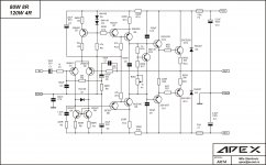
Hi lads, I want 120+ watts per channel at 8ohm. I'm thinking the A40 or A20. Are the parts easily available still? I know the A20 can do 120wpc @ 8ohm and 200wpc @ 4ohm but can't see anything on the A40 output.
I had a look for the 2sa1943 and don't know where to get them, I noticed they are used in the Rotel 1585 5ch 200wpc amplifier.
Also what PSU build and Toroidal is recommended?
Thanks
Kind regards,
Hatless
I had a look for the 2sa1943 and don't know where to get them, I noticed they are used in the Rotel 1585 5ch 200wpc amplifier.
Also what PSU build and Toroidal is recommended?
Thanks
Kind regards,
Hatless
Greetings guys how many watts I need to run 12" 8 ohm 135 mm magnate woofer.mean how many transistors pair to run .
Hello Mile
I took XRK's FH9HV amp boards and ran with simple CRC PSU boards with rails of +/-46vdc. Both the amp boards were running perfectly with my full rangers. Now I wanted to make it a simple integrated amp, so as per the suggestion of XRK got a DACT type 50K volume potentiometer and connected the wiring which also worked perfectly fine. Now during this pot wiring I did pass the input signal wire (hot+ground twisted) between the amp and heat sinks which when powered on I think the wire touched the IRFP240 (positive terminal) legs and because of the heat the shield of the wire melted and shorted the mosfet. I saw that the 220R resistor near the mosfet was burnt up. I immediately switched off the amp and replaced the 220R but now the offset was showing as 16v.
I replaced this IRFP240 mosfet with another genuine one and now the board runs fine. As I have changed one of the IRFP240 mosfets I thought of resetting bias. Using the trimmer on turning one way I could only get it to 6.3mV bias and the trimmer is out of turns. At this bias the offset is -223mV. As suggested by XRK I did the voltage reference test with the ground as the reference on each of the transistors and below are the results. Please let me know what could be the issue as the other board is perfectly fine with 50mV bias and offset being 0.3mV.
BD140 = 43.4v, 13.0v, 42.8v
BD139 = -3.5v, 13.1v, -2.9v
BD139 = -45.0v, -3.5v, -44.6v
IRFP240 = 13.17v, 45.3v, 10.5v (near the positive terminal)
IRFP240 = -3.4v, -45.4v, 0.225v (near the negative terminal)
BC546 = 43.7v, -0.277v, -0.849v (pair thermally coupled)
BC546 = -0.748v, -0.162v, 42.8v (pair thermally coupled)
BC546 = -44.7v, -44.0v, -0.900v
NPSA92 = -44.6v, 43.7v, 44.3v
Thanks
Hi Maniraj,
Please write in the values you measured onto the schematic at the appropriate locations and post the resulting marked up a schematic drawing.
Then we can help you.
One of those MOSFETs needs to be a 9240 P channel.
Please write in the values you measured onto the schematic at the appropriate locations and post the resulting marked up a schematic drawing.
Then we can help you.
One of those MOSFETs needs to be a 9240 P channel.
Last edited:
Hi Maniraj,
Please write in the values you measured onto the schematic at the appropriate locations and post the resulting marked up a schematic drawing.
Then we can help you.
One of those MOSFETs needs to be a 9240 P channel.
Let me find the schematic as with the board that you made it. Will try and post the above results of voltage reference against the ground on the schematic. The resistor near the trimmer is rated 6.8K which I think needs to be changed to a higher value to get some more variance on the trimmer turns to set the bias. As you suggested on the PM I think this resistor needs to be changed to a different value because of the change of the IRFP240 mosfet. And you are right the other mosfet near the negative terminal is in fact IRFP9240. So from my above post the readings should be like these:
BD140 = 43.4v, 13.0v, 42.8v
BD139 = -3.5v, 13.1v, -2.9v
BD139 = -45.0v, -3.5v, -44.6v
IRFP240 = 13.17v, 45.3v, 10.5v (near the positive terminal)
IRFP9240 = -3.4v, -45.4v, 0.225v (near the negative terminal)
BC546 = 43.7v, -0.277v, -0.849v (pair thermally coupled)
BC546 = -0.748v, -0.162v, 42.8v (pair thermally coupled)
BC546 = -44.7v, -44.0v, -0.900v
NPSA92 = -44.6v, 43.7v, 44.3v
Found this amp (cresendo) on flea market in working condition but left ch have some stabillity issues
want to disassmble an remake into apex AF30


instead 2SJ162/2SK1058 will be used 2SJ50/2SK135 which are allready mounted on heatsinks, hoped there no need to change design
Q: did somebody allredy make pcb design, I search for it but zero find
want to disassmble an remake into apex AF30
instead 2SJ162/2SK1058 will be used 2SJ50/2SK135 which are allready mounted on heatsinks, hoped there no need to change design
Q: did somebody allredy make pcb design, I search for it but zero find
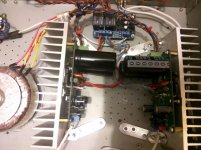
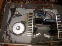
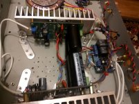
Finally I finished my A40. Found error on PCB... So I have to finished chasi... Small sample how does it sound.. (yes of course It's Youtube and phone record, but sound is great....
YouTube
what was a mistake?
Let me find the schematic as with the board that you made it. Will try and post the above results of voltage reference against the ground on the schematic. The resistor near the trimmer is rated 6.8K which I think needs to be changed to a higher value to get some more variance on the trimmer turns to set the bias. As you suggested on the PM I think this resistor needs to be changed to a different value because of the change of the IRFP240 mosfet. And you are right the other mosfet near the negative terminal is in fact IRFP9240. So from my above post the readings should be like these:
BD140 = 43.4v, 13.0v, 42.8v
BD139 = -3.5v, 13.1v, -2.9v
BD139 = -45.0v, -3.5v, -44.6v
IRFP240 = 13.17v, 45.3v, 10.5v (near the positive terminal)
IRFP9240 = -3.4v, -45.4v, 0.225v (near the negative terminal)
BC546 = 43.7v, -0.277v, -0.849v (pair thermally coupled)
BC546 = -0.748v, -0.162v, 42.8v (pair thermally coupled)
BC546 = -44.7v, -44.0v, -0.900v
NPSA92 = -44.6v, 43.7v, 44.3v
Please transcribe to a redlined drawing of the schematic with all nodes that you measured labeled. That is how we debug this amp, or any amp for that matter. It tells all and there is no guessing what the culprit is. The behavior you show is a very low bias current and might be a bad driver transistor BD139 (one on right) or a burned out resistor (open circuit) or diode. A good way to see the problem is to measure the same nodes on the good channel and write down the numbers in a second schematic. Compare and see where the numbers are way off. You should be able to pinpoint the offending component(s) yourself with this method.
Last edited:
Please transcribe to a redlined drawing of the schematic with all nodes that you measured labeled. That is how we debug this amp, or any amp for that matter. It tells all and there is no guessing what the culprit is. The behavior you show is a very low bias current and might be a bad driver transistor BD139 (one on right) or a burned out resistor (open circuit) or diode. A good way to see the problem is to measure the same nodes on the good channel and write down the numbers in a second schematic. Compare and see where the numbers are way off. You should be able to pinpoint the offending component(s) yourself with this method.
Thanks, yes I am trying to put my measured values against the schematic which was published sometime back. Are you referring to this measured BD139?
BD139 = -3.5v, 13.1v, -2.9v
I will measure the good amp board as you suggested and see the results with differences and by the way many thanks for guiding on this awesome amp.
hello everyone i want to ask about apex a40. what is the purpose of ofset pot? and how to set it? can i use 200r pot?
Offset voltage is the d.c voltage that we can measure in the amplifier out(speaker out) when no speaker connected and the signal input is connected to signal gnd(shorted input), open output.
If an offset trimmer is present the adjustment is for the minimum d.c output.
If an offset trimmer is present the adjustment is for the minimum d.c output.
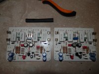
I Made it! Sound great. Thanks for the great scheme. Compared until only Creek 4330 (copy). Creek only wins at high frequencies. Perhaps because the feedback is not yet Silmik2 in apex. The bass is better from the Apex(14). As the wife said, "it's more voluminous bass here, and in Creek it's flat." Immediately began to do the PCB layout with two pairs of output transistors (I have speakers with two 8" bass drivers each).
Attachments
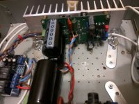
I Made it! Sound great. Thanks for the great scheme. Compared until only Creek 4330 (copy). Creek only wins at high frequencies. Perhaps because the feedback is not yet Silmik2 in apex. The bass is better from the Apex(14). As the wife said, "it's more voluminous bass here, and in Creek it's flat." Immediately began to do the PCB layout with two pairs of output transistors (I have speakers with two 8" bass drivers each).
Remember easy to have better highs when the rest of the sound comes out flat.
Your ears pick up that easily because of only one good thing.
Sometimes it needs some burn in (50-100 hours)the whole sound opens up and became much airy.
I'll prefer better sound all around (including mids and bass) than high frequencies.
 Congrats to your amp
Nice,but what schematic?I Made it! Sound great. Thanks for the great scheme. Compared until only Creek 4330 (copy). Creek only wins at high frequencies. Perhaps because the feedback is not yet Silmik2 in apex. The bass is better from the Apex(14). As the wife said, "it's more voluminous bass here, and in Creek it's flat." Immediately began to do the PCB layout with two pairs of output transistors (I have speakers with two 8" bass drivers each).
gaborbela Thanks!!
you about clone of creek4330 or Apex AX-14?Nice,but what schematic?
gaborbela Thanks!!
you about clone of creek4330 or Apex AX-14?
What amplifier is this?
According to what schematic?
Apex ax-14 - scheme of this theme (it on my Photos).
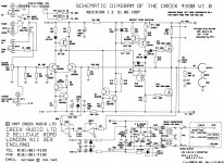
A Creek 4330 from the theme: Creek 4330 bias
A Creek 4330 from the theme: Creek 4330 bias
Attachments
Last edited:
- Home
- Amplifiers
- Solid State
- 100W Ultimate Fidelity Amplifier