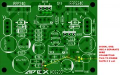
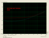
Let's see results after the signal GND modification.
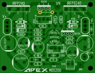
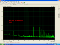
Pictures 6,7,8 are the first test when Power GND & Signal GND are connected together on the pcb.
Picture 9 is the new Steps test.
Pictures 6,7,8 are the first test when Power GND & Signal GND are connected together on the pcb.
Picture 9 is the new Steps test.
Attachments
-
 MOS200 modification.JPG227.3 KB · Views: 955
 -
 8.5V.PNG97.4 KB · Views: 684
 -
 4V.PNG97.6 KB · Views: 683
 -
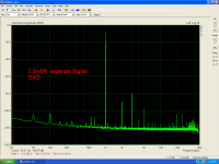
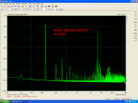 IMD NEW.PNG97.4 KB · Views: 648
 -
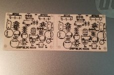
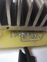 200 MODIFICATION PCB.jpg373 KB · Views: 214
 -
 5.8V.PNG95.4 KB · Views: 196
 -
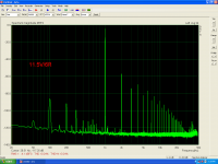 11.5V.PNG96.7 KB · Views: 159
 -
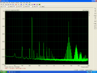 IMD.PNG95.1 KB · Views: 167
 -
 STEPS.PNG61 KB · Views: 169
 -
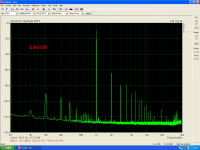
 2.8V.PNG97 KB · Views: 206
Last edited:
Let's see results after the signal GND modification.
Great, What program and hardware do you use to analyze distortion?
Thanks
The software is ARTA.Great, What program and hardware do you use to analyze distortion?
Thanks
The hardware is an Esi Julia pci sound card.
The software is ARTA.
The hardware is an Esi Julia pci sound card.
Thanks
Let's see results after the signal GND modification.
Pictures 6,7,8 are the first test when Power GND & Signal GND are connected together on the pcb.
Picture 9 is the new Steps test.
Do you set DC offset, bias can be set to 50mA and use VAS transistor with higher hfe instead BD139...
Thanks Mile,i don't use trimmer for offset setting yet,but after signal gnd modification offset is 80mV.Do you set DC offset, bias can be set to 50mA and use VAS transistor with higher hfe instead BD139...
I don't use BD139 but i use MJE340.
Last edited:
Thanks Mile,i don't use trimmer for offset setting yet,but after signal gnd modification offset is 80mV.
I don't use BD139 but i use MJE340.
Change 18k resistor to get 3mA for input pair, change 6,8k resistors to get 4mA for VAS transistor, change 47k resistor to set DC offset, use high hfe transistor instead MJE340 and you get better measurements.
Let's see results after the signal GND modification.
Pictures 6,7,8 are the first test when Power GND & Signal GND are connected together on the pcb.
Picture 9 is the new Steps test.
What about sound, this is amp witout global compensation and without VAS miler compensation.
What about sound, this is amp witout global compensation and without VAS miler compensation.
Hi,Mile,i have used 16K AND i measure 48v so 48/16k=3mA for the input trans.
In the VAS i used 5k6+5k6 and i measure 22v so 22/5k6=3.9mA.for the VAS.
Offset is now about 7mV.NO TRIMMER USED.
From an assident the used idle current was very high!
Under these conditions the distortion measurments are excellent!
Unfortunately trying to raise the idle a little further... smoke and flame comes out from the pcb.
A new set of IRF and new zeners installed and now is functional again.
I will post all these tomorrow.
What about sound?
Hm from a little listening,just two or three songs,this amplifier is something different........
I think that i can recognise the Montarbo sound?😉
Bias setting is very sensitive, you can use 220R pot in series with resistor instead 1k.
I was checking my layout to the schematic and I was missing the connection between V+ and the 1k2 and 4007. I have added it here. These should be correct. now. Sorry for any inconvenience.
Attachments

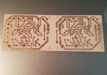
Very nice home etching, Terry. Nice to see you into it again! How many amps sitting around your home now?
Hugh
Hugh
Hi Hugh,Very nice home etching, Terry. Nice to see you into it again! How many amps sitting around your home now?
Hugh
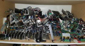
I'm afraid I have way too many. Here is a pic of just one shelf full of tested amps. I have maybe 20 others that are in cases and 4 pair of Slewmaster OPS mounted on large heatsinks for testing Slewmaster front ends.
Attachments
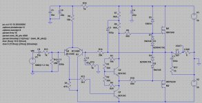
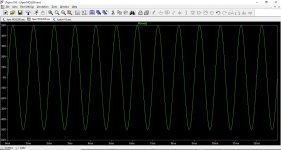
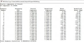
I made a Spice file to test this amp. Here are some screen shots of the results.
Please post the spice file for others to experiment !
Please post the spice file for others to experiment !
My modification.
This amplifier have high THD for my taste, but have good harmonic profile. Slew rate is high enough.
Attachments
Hi Hugh,
I'm afraid I have way too many. Here is a pic of just one shelf full of tested amps. I have maybe 20 others that are in cases and 4 pair of Slewmaster OPS mounted on large heatsinks for testing Slewmaster front ends.
And you still keep on building amps! I thought I had too much junk , I question myself if I m not a hoarder, but when I see what other people have stored over the years, I feel normal again.
- Home
- Amplifiers
- Solid State
- MOSFET Amplifier IRFP240/IRFP9240