The Melbourne ... also needs to be DC coupled to prevent oscillation from LC tank circuit created by output coupling cap and Edcor.
For Melbourne only? Or for all daughter cards?
I've walked an oscilloscope probe down that signal chain many times, while doing square wave testing and plenty of other tests, yet I've never seen any oscillation there, large or small. Not on ANY of the five daughter cards designs that currently ship from the diyAudio Store. Does the quote above include all of them?
Recall that the impedance looking into the primary of the Edcor, is simply the impedance connected to the secondary, divided by the square of the turns ratio. This works out to 650 ohms on the chalkboard, while measurements on the real thing in the real world say 795 ohms, according to Nelson Pass himself (link). It's exceedingly difficult to make the 220uF capacitor resonate with a 650 ohm to 795 ohm series resistance. Was gibt's ?
That kind of oscillation indicates a fault in the daughter card design or in the test bed (amplifier rats nest). Best to understand the root cause of the problem rather than trying to apply a band-aid. Does the Melbourne card still exhibit oscillation at lower gain?
This is useful on the basic M2X with a Tucson even.
The Tucson, both SMD and through-hole have been eerily silent in my build. How would this help?
That kind of oscillation indicates a fault in the daughter card design or in the test bed (amplifier rats nest). Best to understand the root cause of the problem rather than trying to apply a band-aid. Does the Melbourne card still exhibit oscillation at lower gain?
It is specific to the Melbourne when installed inside M2X. When outside and powered by separate PSU and input card removed and bypassed with a cap, it works fine. So some combination of circuit and cap / but I know that removing the 220uF made the screech stop. It’s not MHz oscillation but kHz audible oscillation in form of rail to rail square wave.
I am not saying other input cards have problem at all. Melbourne has 15.6 dB gain (and internal feedbavk) - that may contribute.
The Tucson, both SMD and through-hole have been eerily silent in my build. How would this help?
Only if your build has ground loop hum when connecting both rca’s.
X, it is certainly fun to see a new IPS design being made available for the M2x. I am working on a few designs and design variations of my own, and look forward to eventually sharing those with the community, although in much simpler form.
You have an opportunity to investigate the functionality of the Melbourne daughtercard more completely. Among the IPS designs so far, it is distinguished by having gain higher than the main board itself, as well as a significant amount of local feedback. You have also chosen to use an amplifier which is not typical of the common M2x build as your test bed. The fact that this IPS / main board / PSU system is prone to audio frequency oscillation suggests that the Melbourne implementation is not yet complete, at least in the context in which it was used in this case. Besides the oscillation, the unusual requirement that your input RCAs be grounded to the PSU star ground is cause to look at other ways of implementing your test bed system. Taken together, the issues of oscillation and ground loop hum indicate a system issue with your amp.
You might simplify your work by substituting a more common form of CRC power supply for the SLB, which uses a capacitance multiplier with very little capacitance on its output. Typical M2x builds tend to use a single 300VA or 400VA transformer and a set of 15000 to 22000 uF capacitors on a PCB such as the diyAudio store's Universal Power Supply. If you have the time to make such a system for testing the Melbourne PCBs, then your results will be more applicable to the common M2x built by hobbyists in our community. You may also learn some things which will help make the Melbourne and SLB better designs. It could also be necessary to place capacitance on the order of 10000 uF on the outputs of the SLB power supply to ensure that one of the dominant poles of the amplifier is well below audio frequencies.
I would also note that amplifiers with a total gain of 29dB to 30dB are somewhat uncommon, though I happen to own one myself (Naim NAP 250). Such amps are known for running on the edge of instability, and the Naim design is no exception, being intolerant of speaker cables with higher capacitance and insufficient inductance, and having two layers of over-current protection built into the internal regulator and main amp PCBs. If you intend to advocate the use of the Melbourne daughtercards for hobbyist builds of the M2x, then it would be helpful to fully understand the total set of requirements for such a build to operate without problems. Perhaps a lower gain for the Melbourne, when used as an IPS for the M2x, would be more appropriate to promote trouble-free operation.
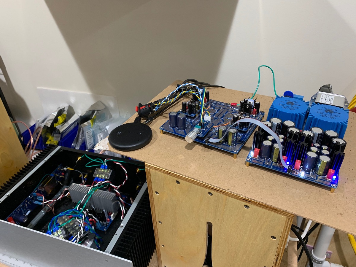
I spent 2-3 years playing around with CRC supplies on the M2 and M2X. Greeted with excessive hum and quite a bit of noise that made the amp quite unusable for my purposes. Many things were required to bring the noise down. The mu-metal shield on the Edcors was instrumental. And now, the SLB was the other piece of the puzzle that finally brought the M2 output noise down to an acceptable 100uV rms spec. I have a P2P implementarion of the Pass F6 style CRCRC which performed the best of all the CRCs. I have 33,000uF x 8 caps on that PSU. It still is not as quiet as the SLB. Let me take a look at the SLB as possible oscillation source - I don’t think it is - but will check.
The Melbourne if trimmed for low DC offset and used DC coupled - should work fine in the M2X as I have shown. The change to the grounding scheme of a star hub is good practice in general for any amp when not using a dual monoblock topology to avoid ground loop hum (caused by fact that the source has a common GND for left and right channel).
If folks want, changing the feedback resistor in the Mel’s to 8k2 rather than 5k6. That will drop gain down a tad.
Here is an interesting data point. If the Melbourne is used in the Yarra preamp motherboard, and then remove the internal M2X input card and connect pins 2 and 4 with a capacitor AC coupling cap, then use the Yarra to drive the M2X’s Edcor directly - no oscillation results.
The YARRA Preamplifier/HPA for Melbourne DB Group Buy
Photo shows 15uF film cap but I also added a 470uF 25v Silmic II there with no issues. It works quite well in this mode as the Melbourne/Yarra has plenty of ability to drive a 600ohm load.
Last edited:
The fact that this IPS / main board / PSU system is prone to audio frequency oscillation suggests that the Melbourne implementation is not yet complete, at least in the context in which it was used in this case. Besides the oscillation, the unusual requirement that your input RCAs be grounded to the PSU star ground is cause to look at other ways of implementing your test bed system. Taken together, the issues of oscillation and ground loop hum indicate a system issue with your amp.
I think that's excellent advice.
Mark Johnson
_
Last edited:
The reason why we like to use a NTC resistor (and not just a 10 ohm resistor) between signal GND and chassis where safety GND is connected…...is that also safety…..if something goes mad?
I know the noise reasons that it is good to have signal GND "lifted" a bit over chassis GND. If something goes wrong then a 10 ohm resistor may just burn but the NTC will act as a short so signal GND becomes chassis GND?
I know the noise reasons that it is good to have signal GND "lifted" a bit over chassis GND. If something goes wrong then a 10 ohm resistor may just burn but the NTC will act as a short so signal GND becomes chassis GND?
Yes, if there is a problem, the nominally higher impedance NTC becomes low impedance upon high currents heating it up. You can also use suitably high current rated anti-parallel diodes for this. 1A10's are handy and also re-wiring a full wave monolithic diode bridge works too. The diodes only let the 10ohm resistor serve as primary ground loop breaker under 0.6v, above that, they conduct.
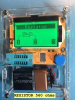
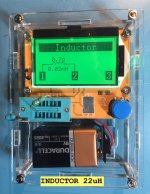
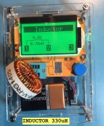
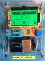
Here are some photos of the Mega328 tester in operation. I encouraged all M2x builders to buy one of these (in post #1885), and gave some eBay links to a few of the hundreds of sellers.
Let me show you some of the measurements it makes for you. Notice that it tells you which pin of the "DUT" (device under test) is connected to which socket number on the tester. This is VERY handy for double checking the pinout of a bipolar transistor: is it BCE? ECB? EBC? The Mega328 gives you the answer.
_
Attachments
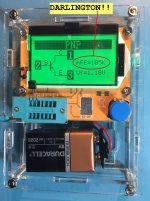
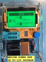

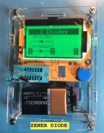
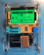
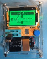
A few more pictures.
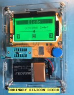
Notice that the tester correctly identifies the Zener diode as two back-to-back diodes with different forward voltage drops. Bravo!
_
Notice that the tester correctly identifies the Zener diode as two back-to-back diodes with different forward voltage drops. Bravo!
_
Attachments
Thanks Mark!
Mine is showing shipped. I should have it before I start the build process.
Links and content pasted into my ever-growing hodgepodge of a "learning guide". 🙄
Mine is showing shipped. I should have it before I start the build process.
Links and content pasted into my ever-growing hodgepodge of a "learning guide". 🙄
The $12.00 Mega328 is not a precision instrument; it was not lovingly hand-built by Bill Hewlett and Dave Packard, and it was not calibrated with NIST certificated lab standards. I treat mine as though it were guaranteed to be accurate within ±10% or ±5% -- but in reality you don't get any guarantee at all on a $12.00 eBay purchase.
Still, it's incredibly useful. I double check every resistor value on the Mega328, five seconds before stuffing and soldering it. When using parts with confusingly similar part numbers (BC327 vs BC337) ; (BC550 vs BC560) ; (ZTX851 vs ZTX951), the Mega328 gives you great reassurance that you do indeed hold a PNP in your hand and not an NPN.
It's also handy when you're slapping together a test circuit on solderless breadboard. You don't need to remember whether the KSA992 pinout is EBC or ECB, and you don't want to stop what you're doing to go look it up. Just pop it in the socket and press the test button. There's your answer.
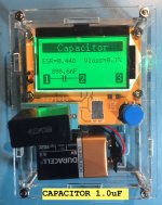
And with teeny tiny little ceramic capacitors (see the photo above of a very small 82pF cap in the test socket), you don't have to put on your head magnifier just to read the tiny numbers painted on the case. Plop it in the Mega328 and ask: is this cap closer to C7=100pF or to C11=3300pF? There's your answer.
And, oh by the way, it's not perfect. The schematic symbol it displays for an Nchannel MOSFET, shows the body diode backwards. 😡 Have a look at the picture above.
Which just means, people make mistakes. Even people who write embedded software for $12.00 electronic gizmos on eBay. Even they make mistakes.
_
Still, it's incredibly useful. I double check every resistor value on the Mega328, five seconds before stuffing and soldering it. When using parts with confusingly similar part numbers (BC327 vs BC337) ; (BC550 vs BC560) ; (ZTX851 vs ZTX951), the Mega328 gives you great reassurance that you do indeed hold a PNP in your hand and not an NPN.
It's also handy when you're slapping together a test circuit on solderless breadboard. You don't need to remember whether the KSA992 pinout is EBC or ECB, and you don't want to stop what you're doing to go look it up. Just pop it in the socket and press the test button. There's your answer.
And with teeny tiny little ceramic capacitors (see the photo above of a very small 82pF cap in the test socket), you don't have to put on your head magnifier just to read the tiny numbers painted on the case. Plop it in the Mega328 and ask: is this cap closer to C7=100pF or to C11=3300pF? There's your answer.
And, oh by the way, it's not perfect. The schematic symbol it displays for an Nchannel MOSFET, shows the body diode backwards. 😡 Have a look at the picture above.
Which just means, people make mistakes. Even people who write embedded software for $12.00 electronic gizmos on eBay. Even they make mistakes.
_
Last edited:
As a curiosity, and since we have discussed problems reading ultra low valued resistors, how does this fare in that realm?
Interesting device, for sure!
Interesting device, for sure!
Haven't tried that yet. I did try a 330 nanohenry inductor. As you might expect after seeing that Mega328 displays inductance in millihenries, it displays the wrong answer on a 330nH = 0.00033 millihenry inductor. It just says zero.
There's probably a min and a max value that it's able to measure and display, for every one of its modes and templates. However for $12 they don't bother to characterize and document them. I bet if you tested a 39V zener diode, for example, Mega328 wouldn't measure the zener voltage correctly, thanks to its 9V battery operated circuitry.
"What does the $12 device do in situation X??"
Spend $12 and try it! It'll be fun!
T
...Which just means, people make mistakes. Even people who write embedded software for $12.00 electronic gizmos on eBay. Even they make mistakes.
<Mark> - Everyone is to leave here immediately... This forum is closed until further notice. Clear the thread at once! ..... I'm SHOCKED-SHOCKED to find errors in a $12 eBay-sold part. ....
<Steward handing Mark his gizmo> Your Mega 328, sir. 😀
As you've said. It's a very cool device for some quick checks. When I even learn what an NPN device is, I'll try it for that function. 😕 I do like that I can use it for bipolar transistors. That should help make sure I get the orientation done properly since you've left flexibility on one of the boards for multiple orientations across manufacturers (I think). The more I learn...
Seriously though, thank you for the recommendation and more-so the understanding that it's not perfect by any stretch.
In the description here of the Mega328 is also mentioned some specifications:
Attention Required! | Cloudflare
Don't know if it is the official.....or it is by using the tester.
Attention Required! | Cloudflare
Don't know if it is the official.....or it is by using the tester.
They are here (Mega328):
Test ranges:
Inductors, capacitors , diodes, dual diode , mos, transistor, SCR , the regulator, LED tube , ESR,
Resistance,Adjustable potentiometer
Resistance :0.1 ohm resolution, maximum 50M ohm
Capacitor :25pf -100,000 uf
Inductors : 0.01mh-20H
Test ranges:
Inductors, capacitors , diodes, dual diode , mos, transistor, SCR , the regulator, LED tube , ESR,
Resistance,Adjustable potentiometer
Resistance :0.1 ohm resolution, maximum 50M ohm
Capacitor :25pf -100,000 uf
Inductors : 0.01mh-20H
- Home
- Amplifiers
- Pass Labs
- The diyAudio First Watt M2x