ggetzoff ,so,You like Mexican Food too? They got some fried Fresh-Cheese Rolls filled with Jalapeno,super.
DT
Taccodude,
Me gustaba comida Mexicano!
So,when I get 44°C on Heatsink with 75mV at 20°C Room Temperatur now,how far can I push it? In Summer I get around 25°C in the House.
regards DT
regards DT
Last edited:
H2
Hi Fab,
At first I want to wish you and of course all others, happy Eastern and a long calm time.
I made a little bit progress with my USSPA, the LDR arrived after a long time and is still build in.
As Project16 I find this is a very good sounding combination, especially heared against a blue Alps attenuator.

Also if the USSPA sounds very good in this stadium, I want to try out what changes if I play around with the Second harmonics. My build is with a 22k resistors for each of R19 and R20, as shown in the circuit diagram and build by a few people.
As a starting point I soldered some short cables to the solder points of the resistors and measured the voltage drop over the two parallel resistors.
The results where 83mV for the left pair and 78,9mV for the right pair ( right channel) and 83,2mV and 79,5mV for the left channel (same position).
What surprised me is the disbalance between the n and p side and on the other side the big similarity between the right and the left channel.
After this I soldered a 220R resistor ( to be on the save side that the parallel resistor value does not go under 20R) in row with a 10kR potentiometer (as intended from the manual).

As results I find that, when I put this combination parallel to the higher voltage drop I could lower this values. Sadly (?!) I could not ecqualize them with the given values for the resistor and potentiometer. I get in the same order as above 80,6mV and 77,7mV such as 80,8mV and 78mV. So I can say that the higher values were lowered around 3mV and the other around 1mV (but I do not know why, measured mor often).
Sadly I am not able to measure the THD directly or to make a Furrier transformation. So I can only measure the values with a Multimeter or use my ears.
Fab is this the way you suggested it (hope so 😀), do you think it is useful to bring the values closer together and when yes how without going over/under the values of the resistors?!
Sound wise it is much better with one 220R resistors (higher voltage drop side) in on part and no resistor in the other part against two 22k resistor (all meant parallel to the 22R).For me the sound seams to be clearer, as take away a pillow and more precious (faster bass).
Does anybody else played around with it?
I only could suggest this to you!
What are your findings?
Regards
André
Hi Fab,
At first I want to wish you and of course all others, happy Eastern and a long calm time.
I made a little bit progress with my USSPA, the LDR arrived after a long time and is still build in.
As Project16 I find this is a very good sounding combination, especially heared against a blue Alps attenuator.
Also if the USSPA sounds very good in this stadium, I want to try out what changes if I play around with the Second harmonics. My build is with a 22k resistors for each of R19 and R20, as shown in the circuit diagram and build by a few people.
As a starting point I soldered some short cables to the solder points of the resistors and measured the voltage drop over the two parallel resistors.
The results where 83mV for the left pair and 78,9mV for the right pair ( right channel) and 83,2mV and 79,5mV for the left channel (same position).
What surprised me is the disbalance between the n and p side and on the other side the big similarity between the right and the left channel.
After this I soldered a 220R resistor ( to be on the save side that the parallel resistor value does not go under 20R) in row with a 10kR potentiometer (as intended from the manual).
As results I find that, when I put this combination parallel to the higher voltage drop I could lower this values. Sadly (?!) I could not ecqualize them with the given values for the resistor and potentiometer. I get in the same order as above 80,6mV and 77,7mV such as 80,8mV and 78mV. So I can say that the higher values were lowered around 3mV and the other around 1mV (but I do not know why, measured mor often).
Sadly I am not able to measure the THD directly or to make a Furrier transformation. So I can only measure the values with a Multimeter or use my ears.
Fab is this the way you suggested it (hope so 😀), do you think it is useful to bring the values closer together and when yes how without going over/under the values of the resistors?!
Sound wise it is much better with one 220R resistors (higher voltage drop side) in on part and no resistor in the other part against two 22k resistor (all meant parallel to the 22R).For me the sound seams to be clearer, as take away a pillow and more precious (faster bass).
Does anybody else played around with it?
I only could suggest this to you!
What are your findings?
Regards
André
So,when I get 44°C on Heatsink with 75mV at 20°C Room Temperatur now,how far can I push it? In Summer I get around 25°C in the House.
regards DT
50c is your max temp. In the hottest section per Fabs manual, section 9.

USSPA
Happy Easter weekend to you Tomtest
You are making really good progress , thanks for posting.
jfet currents equalization is not a defined target since jfet transconductance also plays a role. Transconductance of the N jfet is higher than the P jfet if you look at the datasheet. EUVL member has written a paper on this forum on that subject and the way to use different N jfet and P jfet curves characteristics as opposed to using same jfet IDSS. It is more harder to get a good match like that and very difficult to find someone that will do this match for you. Most people’s find that reasonably close IDSS matched values is correct.
Tweaking the respective jfet current allows to either reduce or increase H2. Without any tweaking you already have a reasonable amount of H2 even with close match of current. I am not able to tell you if you have reduced or increased the H2 with your tweaking because playing with you pot can increase or decrease H2 since you do not know your starting point. You need a THD analyser or go by ear. The point of minimizing H2 is very narrow thus a few 10 ohms range can make quite a difference. Therefore, your sound preference can be either reduced or increased H2.
When I played with this on the USSA3 amp I found that too much H2 was not to my linking.
Fab
Last edited:
ggetzoff I know that with theTemperatur but what I don`t know is ,can I go higher and higher in Bias as long as the Temperatur is ok?
Personally I will not try to go higher because a polarization at 75mV gives if I'm not wrong 1.5A and having 44° in an environment at 20° I already seems high enough, you will also adjust the currents accordingly on the drivers seems to me you.
That's just my opinion.
That's just my opinion.
Last edited:
Personally I will not try to go higher because a polarization at 75mV gives if I'm not wrong 1.5A and having 44° in an environment at 20° I already seems high enough, you will also adjust the currents accordingly on the drivers seems to me you.
That's just my opinion.
Agreed.
If its not sounding warm at 75mV, then something is wrong.
Taccodude
For the max bias I have not analyzed what could happen at > 1.5 A so I can not recommend going higher at this time. Aside temperature behaviour, an high output bias means high driver current so harder loading on input stage too. Regarding temperature, the mosfet temperature is really the one to look at since depending of interface with heatsink there could be several more degrees at mosfet body.
Fab
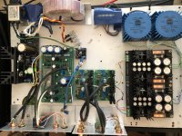
Just got my USSPA driving music (great new Springsteen song), Thanks Fab
Powered by Salas DCSTB, next to the Pass Nutube
First impressions very very good! Idle=Very quiet!
Powered by Salas DCSTB, next to the Pass Nutube
First impressions very very good! Idle=Very quiet!
Attachments
Good job,
I use the same PSU with my USSPA. I don't care what analysis or measurement shows, dual PSUs really help preamp stereo separation and image. I've tried way over built single supplies and it just never sounds as good as dual mono supplies.
Cheers,
Greg
I use the same PSU with my USSPA. I don't care what analysis or measurement shows, dual PSUs really help preamp stereo separation and image. I've tried way over built single supplies and it just never sounds as good as dual mono supplies.
Cheers,
Greg
Thanks Greg,
Have the same opinion on the dual mono power supply, I also use it for the USSA5
Will do some measurements later
Have the same opinion on the dual mono power supply, I also use it for the USSA5
Will do some measurements later
Good job,
I use the same PSU with my USSPA. I don't care what analysis or measurement shows, dual PSUs really help preamp stereo separation and image. I've tried way over built single supplies and it just never sounds as good as dual mono supplies.
Cheers,
Greg
Oh yes
 and a bit more for phono 😉
Hi Asanden,
Since you have 2 very promising pre, it should be interesting to read your personal impression on how the USSPA sounds compared to the B1 Nutube
Since you have 2 very promising pre, it should be interesting to read your personal impression on how the USSPA sounds compared to the B1 Nutube
You are welcome !Just received my USSPA board, Thanks Fab !
Please Keep us posted on your build.
Fab
You are welcome. I am glad you seem to appreciate it so far 🙂Just got my USSPA driving music (great new Springsteen song), Thanks Fab
Powered by Salas DCSTB, next to the Pass Nutube
First impressions very very good! Idle=Very quiet!
Fab
Hi Asanden,
Since you have 2 very promising pre, it should be interesting to read your personal impression on how the USSPA sounds compared to the B1 Nutube
Yes I will do that with my AB instant switch, I need that for proper evaluation...
Will take a while, must be in the mood...
- Home
- Amplifiers
- Solid State
- USSA-5 Build with Review