You should have Grey/purple together and then take Brown to Hot/live and Blue to Neutral.
Not sure that’s what you call it in your Country because I’m in the USA with 120VAC mains.
Not sure that’s what you call it in your Country because I’m in the USA with 120VAC mains.
If you have 245, that’s ~6.5% over rated, which means your secondaries should be at ~25.6vac to start. Again this means something is off, because your 56 measurement is VAC not VDC and too low still.
You should have Grey/purple together and then take Brown to Hot/live and Blue to Neutral.
Not sure that’s what you call it in your Country because I’m in the USA with 120VAC mains.
Yes I have it exactly like that!
I'm trying to power it now!
Nope had to shut it down quick making a crazy buzzing / humming sound.
Might have to call it a day. These late nights can make you do crazy things lol
Might have to call it a day. These late nights can make you do crazy things lol
Attachments


Your mains is very wrong
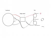
You should have this. Bad drawing but re read my earlier explanation and it should make sense.

You should have this. Bad drawing but re read my earlier explanation and it should make sense.
Check your secondaries!!! You have the Black and Red swapped. Go slow, or you risk damage or worse a bad shock.
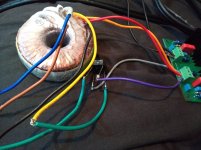
When I put the meter on the - and + of the bridge rectifier I get 56V
Just the bare transformer I get 62V or 2 x 31v. The transformer is only suppose to be 25V.
The transformer is 25V-0V-25V or 50V CT.
UN-loaded, 31V instead of 25V is 24V regulation which is a little poor.
31V AC, withOUT large filter caps, will be a PULSATING wave with "DC" of ideally 0.9 the AC Volts, 28V, which agrees with your 56V both sides.
With large caps it will be 1.414*VAC or, no-load, 44V each side, far past the 35V rating and potentially damaging.
Can you trade for a 20V-0V-20V transformer?
You need to learn how to construct a DC power supply using a transformer. Best thing to do is read some good articles on it, such as these:
Linear Power Supply Design
Power Supply Wiring Guidelines
Short notes:
* AC voltage != DC voltage. DC voltage is AC voltage * 1.414.
* You need capacitors after your rectifier, or your DC voltage will be full of 100Hz buzz which will be useless for an amplifier.
* Amplifiers generally require a symmetrical supply. You have a 0v "centre tap" and then +V and -V around this tap.
* Make sure you have your transformer primary wired correctly for your country. If you have a transformer with 2x115V windings, you need to connect them in series for a 230V country such as the UK.
* Be careful. Power supplies are not forgiving. Get the connections wrong and you can expect smoke. Verify everything thoroughly before you switch on. Consider making a "dim bulb tester".
Last edited:
Thanks for the reply!
Looks like I need some capacitors which I have but now need a 20V transformer. I'm looking into 20v 50va. Guess can't move forward until I get that!
Looks like I need some capacitors which I have but now need a 20V transformer. I'm looking into 20v 50va. Guess can't move forward until I get that!
I found this for £20
Type of transformer: toroidal
Power: 50VA
Primary voltage: 230V AC
Secondary voltage 1: 19V
Secondary voltage 2: 19V
Secondary winding current 1: 1.31A
Secondary winding current 2: 1.31A
Type of transformer: toroidal
Power: 50VA
Primary voltage: 230V AC
Secondary voltage 1: 19V
Secondary voltage 2: 19V
Secondary winding current 1: 1.31A
Secondary winding current 2: 1.31A
You could also buy a variable power supply that uses LM317 and LM377 with your current transformer which will have input caps (small ones) already on the board. Just adjust down to +/-28 VDC on the output and you are ready to go. Should be less than a new transformer.
You could also buy a variable power supply that uses LM317 and LM377 with your current transformer which will have input caps (small ones) already on the board. Just adjust down to +/-28 VDC on the output and you are ready to go. Should be less than a new transformer.
Thanks will look into that! I cant order till Tuesday due to Bank holiday
Look at these - this is typical version and should be fine for your application as well (easy to add caps if you feel it's needed later on). There are many others all all price points - so you can decide which is best for you.
LM317T LM337T 317 337 Power Supply Dual Voltage Regulator Adjust Board DIY Kits 699939547238 | eBay
LM317T LM337T 317 337 Power Supply Dual Voltage Regulator Adjust Board DIY Kits 699939547238 | eBay
Just the bare transformer I get 62V or 2 x 31v. The transformer is only suppose to be 25V. But I have read it can go down when load is attached.
Your transformer has dual secondaries with a center tap. The center tap should be grounded, then you have 2 x 25 (or 33) on each side. That should go into a full wave rectifier, feeding some serious capacitance as noted. Google full wave rectifier with center-tapped secondary.
If, like you have done, you rectify the entire secondary you end up with double the intended voltage.
Jan
Last edited:
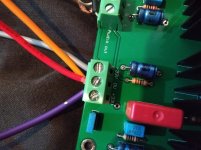
Do you have a picture of the downside, backside of the board?
I am looking for a way to adjust the current. By swapping 2 resistors per channel. You could adjust the current, to get optimal power dissipation of these small heat sinks, at voltages 10 - 40 V for example.

- Home
- Amplifiers
- Solid State
- Class A board DOA33. PSU Help!