Did you measure this?
The Fairchild
LM7815 spec says 90uV/Vo in a 10-100KHz BW = 1.35mV
LM317 spec says 0.003%/Vo in a 10-10KHz BW = 450uV
The specs are not comparing the same measurement BW but ...
I have a HP/Agilent 11715A AM/FM test source that was used to measure a 8901A,B modulation analyzers phase noise or residual FM. They had a mod to upgrade it, change out LM78(9)xx for LM317/337, I wonder why they did that? I assume it was done to reduce the phase noise of the oscillators. They constructed the units RF section, to float on rubber shock absorbers, used feed thru caps to wire the supplies into the RF enclosure, used cap multipliers on each supply inside the enclosure. That is what I call a well designed PS for sensitive RF circuits. It also had a RFI line filter. I think the PS design should work well for audio frequencies too 🙂 11715A has a FM band modulator, that I use to test align low thd Fm detectors in tuners.
No. The data sheet says Vn = 90uV 10Hz to 100 kHz at 25 deg C
It would have to be an extraordinarily bad linear regulator to specify the noise at 90uV/Vo.
Are we looking at the same data sheet? (I'm looking at the FSC one via Mouser)
just no output 🙂))
As predicted. So my soft ignore (just scroll fast) is still relevant.
//
Dreamth, you appear to not understand dielectric absorption (DA) in caps. This does not measure effectively with sine waves. You need special test waveforms. Do you know what I am talking about?
So true.You know how to make a small fortune in audio.: you start with a big one!
Dreamth, I gave an example of why HP needed a low noise regulator in the 11715A.
Was under the impression a 317 was quieter than a lm78xx.
Looked at the first LM78xxx I could find, it is older, version march 2008, I'll look at a newer one. TI says 90uV for uA7815, we found a mistake in the old data sheet 🙂
Was under the impression a 317 was quieter than a lm78xx.
Looked at the first LM78xxx I could find, it is older, version march 2008, I'll look at a newer one. TI says 90uV for uA7815, we found a mistake in the old data sheet 🙂
Thanks for the advice Richard. I have been using dummy load resistors on the output of my regs for about 15yrs now with good results. I like the idea of a pre-reg also.
Thats about the time I published it in an article called Power-Up... an overview of power supplies ..... in TAA.
Enjoy....
-Richard
Last edited:
Of course.We have emphasized the importance of controlled listening tests quite frequently over the years.
This said, if controlled listening test are useful for scientific statistical studies, what their need in the process of voicing a gear during a design work of an audio product ?
When differences between two solutions are obvious, no need to "controlled listening tests". (Like blind or ABX)
When they are not, we need-it and... use it. (to chose a component, by example, but... the question of the quality / price ratio will arise first)
-Controlled listening tests are complicated and tiring. And those complicated procedures and the fatigue they cause tend to decrease our sensibility. So the result will often do not learn us much more.
-During the process to improve a design, if improvement in the listening comparison is not obvious, why not to begin first to improve parts ... that can be improved in a more obvious way: They usually exist in a large enough proportion to focus our attention in priority.
Ok, we are in the lounge. I have a little story from my experience of the day.
I received this morning my first streamer. A little Chromecast audio. So happy to put a foot in the 21th century.
Plugged-it to my computer, played-it after half an hour of readings, searching cables and so, understanding the way to pair-it etc...
Oh the sound on my little PC speakers looked like quite clear and good. So, i tried to set the things in order to make a test in the big system in my listening room next door. Impatient.
I just wanted to play a FLAC file that is in my network's computer, with my smartphone as a remote. The most basic use of such a device, not ?
Making the story short, after hours of fight with Google broken links where was supposed to be ... the user manual (only commercials BS when not broken), googling on dozen how-to videos made by kids, installed several apps on my smartphone that are all most unusable the ones of the other, I realized that I had no simple ways to browse my own folder with my own recordings appart ...to pay a monthly bill to Google. Or to click on the play button in a screen of my computer, then run in the other room to listen to the tune.
I promise-you, at the end of the day, I was not interested any more to make blind tests between my actual DAC and the one of this Chromecast device.
Rather interested in the means to fire the head quarters of Google.
See what I mean on a philosophical and political point of view ?
Last edited:
But people claiming to be objectionists representing the scientific basis have a bigger obligation to bring real science to the table.
Bigger than who? I have no problem with equally applied standards. IMO SY's capacitor findings are of equal value to the capacitor rolling prose that appears here much of the time.
SYclotron Audio | Sigh, more capacitor nonsense
...SY's capacitor findings are of equal value to the capacitor rolling prose...
A guy measures something he knows how to measure, another guy judges the sound of something he hears. Equal value in what way? Moral value?
A guy measures something he knows how to measure, another guy judges the sound of something he hears. Equal value in what way? Moral value?
I agree that they aren't equal in value; the subjective judgement is likely worthless. 🙂
There are so many amazing threads here where people replace functional decoupling caps with huge film "audio" electrolytic caps via 2 inch leads. Of course, it always sounds fantastic after.
There are so many amazing threads here where people replace functional decoupling caps with huge film "audio" electrolytic caps via 2 inch leads. Of course, it always sounds fantastic after.
Perhaps you don't like exaggerated claims?
I know ...I was just reading your pdf document and i got over your slew rate test (3.5 us...10us), but capacitors charge discharge process is faster than sinus waveform which the actual music is, complex, but still sinus and anyway the highest slew rate of a sinus waveform is in the zero crossing region where the dielectric absorption is minimal. Maybe it's just QSC which are stressing their coupling capacitors at the highest levels possible and still their distortion levels are very small.Dreamth, you appear to not understand dielectric absorption (DA) in caps. This does not measure effectively with sine waves. You need special test waveforms. Do you know what I am talking about?
Please look at an older phono preamp i made in 2014 and see the measurements.At the time i changed a valve stage with a higher transconductance stage based on transistors and the response changed from max 10khz square wave to 20 khz square wave. I shouldn't hear the difference but i did, just that i modified the amp's slew rate, not the signal slew rate .I couldn't explain that either. The sinus signal tests modified visibly on the scope at 480khz with the last modification.It had no feedback so it was easier to work on. The Problem:
I was measuring that response through an anti-riaa filter, two coupling capacitors and a passive riaa filter:The input signal was 5 v rms i think...i don't remember exactly i just used a home made generator.
https://www.diyaudio.com/forums/analogue-source/255149-unu-pnono-riaa-mm-preamp.html#post3935638 If you're curious you can see what i did later changing the riaa filter .The square freq response was identical but the sound changed.It sounded a bit more cleaner but lost some vibrant effect, it was lifeless.
Slew rate is easily seen in two different issues of silicon amplifiers : crossover distortion and generating high order harmonics when feedback is applied with a lag. There's also a problem of slew rate when the signal is compressed or clipped due to rail or ouput loading, but that is a different problem and usually is producing loads of h2 and h3 in the first place.
Valve amplifiers using output transformers can't be blamed for huge slew rates even if they have no feedback at all, but they easily solve the crossover distortions.
What valve amplifiers using output transformers have is a sliding band centered around the fundamental with the highest energy , which cuts in a very effective way the higher order harmonics energy .
For that there's a patent explaining it : Semiconductor amplifier with tube amplifier characteristics - PRITCHARD; ERIC K.
With silicon transistors we have very different problems and slew rate becomes more important , but it's related to the phase lag in the system due to parts of the circuit being slower before applying feedback while the capacitors can be at the input and output , not included in the feedback loop.
They will hardly make a bad sound unless they really are bad or they don't have the right value according to the load impedance. Doug Self said that in order to make distortions lower , making the electrolitic max voltage higher doesn't help, just making the capacitor's value higher is a solution.Tried that and it works.
Bigger value capacitors is clearly the stupid man's best tweaking for such cases... It didn't work with my 250 ohms headphones though...I couldn't use more that 3000 uf NM bipolars ...so i keep my tpa6120 directly coupled to the headphones.But that was about the low end of the spectrum, hardly related to the slew rate.
With fet input or even high impedance bipolar circuits...there's no such problem.You never hear a coupling capacitor in high impedance circuits.
By the way...I opened the most professional sony DAT machines, the best cassette players, the best cd players, the best dvd players and they were literally full of Nichicon muse bipolars and pretty much every high end equipment i saw used them or Elna caps at least one at the output so what musical source did we use for 30 years in the digital era?
I can't blame you for anything, but most of the people on Earth used to listen Marantz, Sony, Phillips , Aiwa, Nakamichi, Yamaha which used lots of Nichicon bipolars in their most expensive and performant designs. Kenwood used Elna and they were the most minimal at using capacitors in the signal path . In my favourite amp, Kenwood only use one capacitor at the phono output , but they indeed have designs with no capacitors at all and they didn't make Accuphase for nothing. They needed to sell current feedback and capacitorless designs. Maybe that is why i like the most their amps, but they still use a tone stack in the feedback network and a special rc network for reading the speakers back emf through two additional wires .
Maybe Mark Levinson is better...I may never know cause i can't afford it , for now i can't even afford an inguinal hernia surgery, but until then, i'm very pleased with the sound i can get with some capacitors in the signal path and many others think like me...
Attachments
Last edited:
Ah... thats progress, perhaps. Mine from actual measured results:
View attachment 751013
Again the truth is in the details --- Your's are "C" weighted (cheating).
THx-RNMarsh
Getting back to some technical topics.
Here is a real measurement of Kyocera K50 series 24.576 MHz XO performed by an Agilent E5052A (courtesy of member davecandialex).
This is a $2 SMD XO.
I also looked at close up pictures of the Benchmark DAC3 PCB and read the markings off the 6 XOs and they are all CTS CB3 series parts.
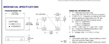
https://www.ctscorp.com/wp-content/uploads/2015/11/008-0256-0.pdf
Cost is around $1.70 from DigiKey in qty 1. Does not even specify phase noise vs frequency other than a 12kHz - 20MHz jitter spec.
Maybe the clock obsessed can explain how the Benchmark be any good using such pedestrian oscillators.
Perhaps it's yet another BS narrative created by those with a vested interest in selling clocks or differentiating their product.
I also looked at close up pictures of the Benchmark DAC3 PCB and read the markings off the 6 XOs and they are all CTS CB3 series parts.
The one next to the dac chip in the pic below looks like CTS CB3?
Attachments
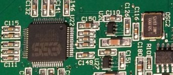
The one next to the dac chip in the pic below looks like CTS CB3?
It looks like it, but the markings are slightly different than the pic I saw. Might be a different version of the DAC or PCB. Same footprint and 50M frequency though.
This pic shows it more clearly:
https://3.bp.blogspot.com/-Qk6AkOJh...yhd9fGmd72ioQCLcBGAs/s1600/DAC3DX+inside+.jpg
Last edited:
Markings of the CTS chip you linked to attached below. Doesn't look anything like the clock marking in the pic I posted.
The clock in the pic only has two lines of print. There is a decimal point in frequency rather than an M, etc.
It does appear to be a different part. It's clearly visible in the pic I posted, though.
You'll also note there are more than 1 version of the markings, and the OSC2 has the M in it in the pic I posted. It's possible some of them are older or from a different facility.
Last edited:
It does appear to be a different part. It's clearly visible in the pic I posted, though.
I don't think that's a production DAC-3 in that pic, at least the back panel layout in that picture is not like the DAC-3 that I have. It might have been a mock up or a prototype, I would guess.
Last edited:
That's not a production DAC-3 in that pic, at least the back panel layout in that picture is not like the DAC-3 that I have. It might have been a mock up or a prototype, I would guess.
It's the DX model according to the site I found it on.
There might be more than one source of XOs, not uncommon.
The part in your pic is from MEC (Mercury Crystal)
Mercury Electronic Ind Co.,Ltd
- Status
- Not open for further replies.
- Home
- Member Areas
- The Lounge
- John Curl's Blowtorch preamplifier part III