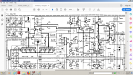
Just a discrete opamp, NJFET LTP, followed by PNP LTP with NPN current mirror.
Then diode biased Darlington complementary emitter follower.
Then NFB loop.
As to folded cascode, you might be interested to take a look here :
https://www.diyaudio.com/forums/hea...lded-cascode-headphone-amp-3.html#post1739927
(Post #143)
Patrick
Then diode biased Darlington complementary emitter follower.
Then NFB loop.
As to folded cascode, you might be interested to take a look here :
https://www.diyaudio.com/forums/hea...lded-cascode-headphone-amp-3.html#post1739927
(Post #143)
Patrick
Well...that "just a ..." happens to be one of the best voltage feedback design for a phono amp ever made.It just takes in consideration all the basics rules of a voltage feedback design for the purpose of amplifying a phono cartridge.The only thing that is missing is a capacitance compensation switch, but that capacitor is often formed by the input cable .
Attachments

Well...i can say whatever i think, but now you're using an argument of authority with a little bit of humour.If you say so. 🙂
Patrick
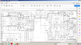
That phono preamp was made by the same guys who founded Accuphase , the Kensonic team who built all the Kenwood L-line including this amp and its preamp:
Attachments
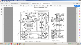
Accuphase switched completely , literally over the night , to current feedback amplifiers for the power section because of the "audiophile press " pressure which was heavily praising current feedback architecture's benefit in the 70's just as it does today discarding any possible good vfb design , but never abandoned the voltage feedback for the phono section although the phono section had the highest dynamic range to cover at a fixed gain for any input.
The choice couldn't be more toxic when based on audiophile press, often payed big money to tell a lot of BS.
The choice couldn't be more toxic when based on audiophile press, often payed big money to tell a lot of BS.
Last edited:
Just good old days clamping...
1S2076 datasheet(2/6 Pages) HITACHI | Silicon Epitaxial Planar Diode for Various Detector, Modulator, Demodulator
1S2076 datasheet(2/6 Pages) HITACHI | Silicon Epitaxial Planar Diode for Various Detector, Modulator, Demodulator
Just far too complex for my liking, but then I am a ‘reductionist’. If you keep adding parts for no hearable or measurable improvement what’s the point? And I have to say, Japanese products from the ‘70’s and ‘80’s were the worst offenders in this regard.
🙂
🙂
Looks a lot like the Yamaha C4; probably contemporary. None of those 1980's Japanese circuits would get within hollering distance of John's suggested device stage count.
Bill has suggested that piece of mind be factored in. Others may argue directly for beauty or elegance of design. I think maybe some of the fear of 8-leggers is the inability to see what's under the hood. How can it be beautiful if I can't see it?
Audio equipment as Art leads to some scarily incompetent equipment all too often these days (sadly, often involving vacuum valves), but we're all searching for various intangibles in our work. We're all taking our own chisels to the not-a-horse parts of the marble, hoping to leave beauty intact.
All good fortune,
Chris
Yes, it has been proven that the "audiophile press" is in the hands of the Illuminati.Accuphase switched completely , literally over the night , to current feedback amplifiers for the power section because of the "audiophile press " pressure which was heavily praising current feedback architecture's benefit in the 70's just as it does today discarding any possible good vfb design , but never abandoned the voltage feedback for the phono section although the phono section had the highest dynamic range to cover at a fixed gain for any input.
The choice couldn't be more toxic when based on audiophile press, often payed big money to tell a lot of BS.
But we know the truth about this plot. Let's eradicate the CFAs and others Class D amps from the surface of the earth and save the holy "Long tailed pair" from destruction.
Last edited:
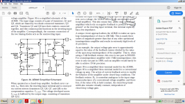
Here is the "perfect" topology from which others are derived. See Fig 5 and 10. I created/developed it in the late 70's. Published in 1980.
Minimal parts count. Operating behaviour is Current-Mode. Output idle was 23mA. 2N2219A/2N2905A curve-tracer matched to be identical, the distortion is almost unmeasureable. For the era, it was quit advanced. Add diode to second stage (current-mirror Q3,5), and then add diamond I/O stage and you have todays' popular topology for a CFB amplifier.
View attachment MarshPreamp.pdf
As historical fact -- D.Nelson (Comlinear) contacted me by phone after I published the circuit. He added the diode etal and got patent filed in 1983. First IC with Elantec in 1987.

Your welcome.
I still prefer the original circuit with 2 gain stages. Now I add an output buffer, usually, for low Z loads Such as for a headphone amp.
THx-RNMarsh
Minimal parts count. Operating behaviour is Current-Mode. Output idle was 23mA. 2N2219A/2N2905A curve-tracer matched to be identical, the distortion is almost unmeasureable. For the era, it was quit advanced. Add diode to second stage (current-mirror Q3,5), and then add diamond I/O stage and you have todays' popular topology for a CFB amplifier.
View attachment MarshPreamp.pdf
As historical fact -- D.Nelson (Comlinear) contacted me by phone after I published the circuit. He added the diode etal and got patent filed in 1983. First IC with Elantec in 1987.
Your welcome.
I still prefer the original circuit with 2 gain stages. Now I add an output buffer, usually, for low Z loads Such as for a headphone amp.
THx-RNMarsh
Last edited:
Here is the "perfect" topology from which others are derived.
(...)
As historical fact -- D.Nelson (Comlinear) contacted me by phone after I published the circuit. He added the diode etal and got patent filed in 1983. First IC with Elantec in 1987
You missed quoting:
Frederick E. Terman, "Feedback Amplifier Design," Electronics, January 1937, pp. 12-15, 50.
J. O. Edson and H. H. Henning, "Broadband Codecs for an Experimental 224Mb/s PCM Terminal," Bell System Technical Journal, Vol. 44, No. 9, November 1965, pp. 1887-1950.
You inventing the CFA topology, ahem,....

I was already into the 8 leg solution in 1980 except for my Bonsai 4 transistor phono amp which was pretty much like the generic 4 transistor EQ amp of the day!
Good see some of these old designs Richard!
Good see some of these old designs Richard!
- Status
- Not open for further replies.
- Home
- Member Areas
- The Lounge
- John Curl's Blowtorch preamplifier part III