Good to see an old big spider 🙂I was already into the 8 leg solution in 1980]
You missed quoting:
Frederick E. Terman, "Feedback Amplifier Design," Electronics, January 1937, pp. 12-15, 50.
J. O. Edson and H. H. Henning, "Broadband Codecs for an Experimental 224Mb/s PCM Terminal," Bell System Technical Journal, Vol. 44, No. 9, November 1965, pp. 1887-1950.
You inventing the CFA topology, ahem,....
I might add Nelson's patent does not claim the basic topology, that's why no IC CFA's ever owed any royalties to Comlinear. Too bad the guys at Harris were not on the ball.
Last edited:
You missed quoting:
Frederick E. Terman, "Feedback Amplifier Design," Electronics, January 1937, pp. 12-15, 50.
J. O. Edson and H. H. Henning, "Broadband Codecs for an Experimental 224Mb/s PCM Terminal," Bell System Technical Journal, Vol. 44, No. 9, November 1965, pp. 1887-1950.
You inventing the CFA topology, ahem,....
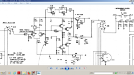
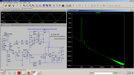
It is the perfect topology IMHO. And follows along what JC said... fewest parts. 4 transistors. Operating in the current-mode region it has ultra low THD and ultra wide band width. Moderate gain. Add diode for second stage mirror for the patent. then add diamond input and output and you have todays IC's etc. But for an audio amplifier, the 4 transistor original gives excellent performance and sound.
View attachment 4 xistor amp.pdf
THx-RNMarsh
Last edited:
It is the perfect topology IMHO.
(...)
But for an audio amplifier, the 4 transistor original gives excellent performance and sound.
Don’t know about the audio performance, but given the performance and properties of our organic Fourier analyzer, I am no longer surprised by any outstanding claim.
Otherwise, to me, by any engineering metric, the circuit is an insult. As much as the JC basic topology, used and re-used in the last 50 years.
I might add Nelson's patent does not claim the basic topology, that's why no IC CFA's ever owed any royalties to Comlinear. Too bad the guys at Harris were not on the ball.
Dont know NP's circuit you are refering to .... but yes, Comlinear could not claim the basic topology. Rather a mod to it. perhaps an important mod as it is used more than any other CFA.
I would prefer my original topology for line stage. But the Comlinear mod for power amps.
As Bonsai has accurately described at his web site, the feature of the Current-Mode operation is important here. Not only the topology is minimalist but mine and Comlinear's was running in CMA mode of operation. Others referred to in lit where not.
A very very general clue I can suggest without a circuit analysis would be to look at the circuit Z's and currents. Low Z and high currents may = CMode and fast, wide bandwidth.
I used high currents and low Z values. The highest Z is 1K. I also used +/- 24vDC supplies. Typical small IC package dissipation limitations etc can not do this... but to get around the high idle currents, diamond buffers would supply high peak currents on demand.
THx-RNMarsh
Last edited:
Don’t know about the audio performance, but given the performance and properties of our organic Fourier analyzer, I am no longer surprised by any outstanding claim.
Otherwise, to me, by any engineering metric, the circuit is an insult. As much as the JC basic topology, used and re-used in the last 50 years.
Sorry to insult you :-( I even "improved" this concept circuit later by cascoding, current sources etc. But it still was operating in Current-Mode.
All the "improvements" to date are great and I watched and read about them. But for sound, performance and simplicity, the 4 basic transistor model is hard to beat.
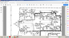
Here is another variation of that basic topology:
View attachment Marsh HPA-7.pdf
(<.001% THD into 32 Ohms)
THx-RNMarsh
Last edited:
Dont know NP's circuit you are refering to ....
Different Nelson, I'm pretty sure...

I've read "The Audio Amateur" and a lot of these threads enough that I could give technical justifications for those transistors. I'm less confident in how much they'd do for the actual sound.Just far too complex for my liking, but then I am a ‘reductionist’. If you keep adding parts for no hearable or measurable improvement what’s the point? And I have to say, Japanese products from the ‘70’s and ‘80’s were the worst offenders in this regard.
🙂
I'm also recalling some time around 1970 tracing through my sister's "Eight Transistor" handheld radio, there were two transistors that I looked at over and over again, and couldn't tell what they were doing in the circuit. It took way too long to learn their true purpose was for marketing reasons.
... Otherwise, to me, by any engineering metric, the circuit is an insult. As much as the JC basic topology, used and re-used in the last 50 years.
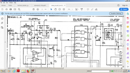
For obvious reasons, this circuit is NOT an insult, and the same goes for all others here.

For obvious reasons, this circuit is NOT an insult, and the same goes for all others here.
I can only hope you noticed the obvious fixes for all the original circuit topology shortcomings, with the exception of the poor PSRR, hence the power supply buffers.
For a version with a PSRR fix, see https://www.diyaudio.com/forums/analogue-source/333000-hps-6-1-a.html#post5675186
For obvious reasons, this circuit is NOT an insult, and the same goes for all others .
I dont see anything at all new here. Variation on what JC has been doing and showing. Albeit with a lot more lipstick on it.
Complimentary jfet... paralleled, cascoded. Big deal. Nothing new there. Folded cascode. Nothing new. Oh. an opamp. wow.
BTW -- when I cascoded and current sourced the 4 transistor circuit et al... it didnt sound better with the loudspeakers of the day. JC already told you to use as few parts as possible which gets the job done will sound best. Maybe you thought I was going to show my best work to you? hahaha. I dont think so. I did what JC does... showed the creation from some 40 Years ago. I was about 30 years old then. I am 74 now. Lots of great CFB IC and discrete now.
Show me something new. A circuit trick, maybe. A useful mod. Distortion numbers. A patent.
THx-RNMarsh
Last edited:
It's all about the higher authority of the feedback network over the input in fact and Holman applied this in his APT voltage feedback design.
But then...if we're talking about lower count component designs i will show you two commercial designs that are very hard to beat: Harman Kardon 645 vxi and Aiwa c-22
both discussed here in detail : Modified aiwa riaa j-fet phono preamp. You'll see there how i made the HK design even lower count design by using an op-amp and a fet at the input .I used that design for a cassette player tapehead preamp and it worked very well actually, just not lower noise then a classical transimpedance Nakamichi design because of the collector resistor in the lower bjt transistor.That could have been absent just the distortion would have risen up a bit...
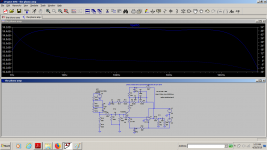
I uploaded also two sim for a modified version of aiwa c-22 only for the power supply as i already failed with a fet input in getting a better sound than the original design could get me with all the simulations and better components .I thought that the input capacitor or the use of a low noise fet would make any improvement in the design, but it was not the case, just tougher useless job.There's no audible distortion due to the capacitor at the input for an mm cart.
But then...if we're talking about lower count component designs i will show you two commercial designs that are very hard to beat: Harman Kardon 645 vxi and Aiwa c-22
both discussed here in detail : Modified aiwa riaa j-fet phono preamp. You'll see there how i made the HK design even lower count design by using an op-amp and a fet at the input .I used that design for a cassette player tapehead preamp and it worked very well actually, just not lower noise then a classical transimpedance Nakamichi design because of the collector resistor in the lower bjt transistor.That could have been absent just the distortion would have risen up a bit...
I uploaded also two sim for a modified version of aiwa c-22 only for the power supply as i already failed with a fet input in getting a better sound than the original design could get me with all the simulations and better components .I thought that the input capacitor or the use of a low noise fet would make any improvement in the design, but it was not the case, just tougher useless job.There's no audible distortion due to the capacitor at the input for an mm cart.
Attachments
Last edited:
Bill has suggested that piece of mind be factored in. Others may argue directly for beauty or elegance of design. I think maybe some of the fear of 8-leggers is the inability to see what's under the hood. How can it be beautiful if I can't see it?
Placebo effect is real and proven. I see little point in not welcoming it with open arms 😀.
Ed: Sorry been useless at advice last few days as manic weekend, but others cleverer than me have pointed you in the right direction!
I dont see anything at all new here.
Q.E.D. (Quod Erat Demonstrandum) 😉
I dont see anything at all new here.
(...)
Show me something new. A circuit trick, maybe. A useful mod. Distortion numbers. A patent.
So indeed you appear to claim inventing the current feedback topology, as long that anything resembling your 1980 audio circuit is declared as not new. You think you are one of those forgotten developers that history did not reward with the position they believe they deserve.
Then bringing the universal “no win” argument of “doesn’t sound right” based on “because I say so” and a name dropping (John Curl), hoping to bring an authority based argument.
Nothing new in this approach. Show me something new. At least you got from me the trick of an interesting servo approach. And it’s free of any claims.
P.S. Look closer at the web site where the schematic was ripped from. You’ll find more numbers that you are prepared to digest.
Last edited:
Richard N. Marsh Inventions, Patents and Patent Applications - Justia Patents Search
Is this our Marsh? Indeed, i couldn't see anything about audio or current feedback , but he may have been working for somebody else at the time...
Is this our Marsh? Indeed, i couldn't see anything about audio or current feedback , but he may have been working for somebody else at the time...
Last edited:
May-be it is not the circuit, that is an insult, but your agressive, rude and unfriendly repetitive behavior ?Don’t know about the audio performance, but given the performance and properties of our organic Fourier analyzer, I am no longer surprised by any outstanding claim.
Otherwise, to me, by any engineering metric, the circuit is an insult. As much as the JC basic topology, used and re-used in the last 50 years.
This said, If you have any technical arguments to justify your hateful comments, they are welcome. Because your personal opinion does not weigh as much as you think.
Strange, as I can see the word "Audio" repeated many times.
- Status
- Not open for further replies.
- Home
- Member Areas
- The Lounge
- John Curl's Blowtorch preamplifier part III