I will celebrate my day as I hope many of you do in the best way, listening to good music.
PS: for some reason that I do not know, my emotional amygdala does not send me the May 1 to the heroes of Chicago but to the song (and the movie) about Sacco and Vanzetti
I leave the version of Joan Baez, yes, the chorus is a bit repetitive, nothing is perfect
Will I have to write to Goleman to thank him? I have been beaten for free again and it has not made a dent !
YouTube
Click with confidence, the computer viruses are transmitted when they open the .exe, like this ..... 😱
Sorry, I can't understand your point, mister.
To show you that electrons dont have to move in different " rythyms".
It is a reasonable assumption.
The only place I can think is different, if the entire wire is engaged in the bottom frequency, then the current density at the surface cannot have a pure square wave current vs time as not all the lf current is there.. My take would be the density at the surface might look more high pass.
Course, since I can no longer do that math, and cannot think of any possible way of measuring it, I'm happy to just wave my hands about...😀
jn
Right, surface looks high pass because the high freq. from the centre has move outside. Centre looks low pass, And somewhere in the middle there should be a square wave current density?
🙂ELECTRONS DONT LOVE EACH OTHER.
- so how can people love each other? That can be a source of all human wars.
Sory for off-top. 🙂
Not actually sure. Sounds good, but maxwell's equations rule..could be different. We're both just guessing..Right, surface looks high pass because the high freq. from the centre has move outside. Centre looks low pass, And somewhere in the middle there should be a square wave current density?
jn
My take on skin depth. Quick (very) drawing of current densities for a square wave, many harmonics, from skin effect....
True; except you show 20KHz gone down to nearly ZERO. Skin effect is typically a small effect. For it to matter, the conductor must already be mighty small for the load.
When I design floor framing, I figure the furniture, people, dogs, and allow a round number for the floor finish (boards, plywood, carpet). It typically does not matter if I assumed thin carpet and end up with thick oak.
In almost all practical cases, cable Inductance rolls-off the highs before Skin effect starts to show.
Also: we typically pick a Hi-Fi speaker cable for <0.1 Ohms resistance, so we get low-low loss into 8 Ohms and specifically Damping Factor near 80. If the impedance at 20KHz rises to 0.2 Ohms, in pure 8 Ohm load that is 0.1dB "error" which is swamped by erratic response and dispersion from real speakers. A typical speaker is NOT 8 Ohms at the frequency extremes, and often 2X nominal, in which case a small rise of line impedance does even less harm.
I never gave a frequency thinking more in MHz where it actually matters. I agree with everything you've said, my little drawing was just a mental exercise to show that electrons don't move at different "rhythms" if there's more than one frequency. As in some electrons move at one freq. others at the other freq.
For the fun I replaced my speaker cables. From calculations about the dumping factor, I found I could gain a little bit.
So I ordered 10 meter of 2 x 2.5mm2 cable.
So thick, I had a hard time to shove them in the amp's terminals. Glad I did not go for 2 x 4mm2...
Putting back on power, I had only one of the two channels working.....😡
I cursed, I had fried an amp going at a too low resistance, a totally stupid idea. I messed for a while, opening the amp for some blown fuse. This shows how strong placebo effect can be.
Finally that was just a bad contact in a speaker terminal.
Then, there was absolutely no audible difference from the old speaker wires made from electric lamp cord....Even thinking about the improved dumping factor, well, here placebo effect had failed.
And I had good 😀 wires: Tin coated multi brand copper.
May be I went wrong not adjusting the right and left for accurate equal lengh 🙂 but making a shorter one for the closer speaker.
Anway, I like their stiffness and look, the transparent isulation makes the wires inside look thicker.
You didn't hear a difference because the wires need cryogenic treatment.
BIS Audio | THE PowerBIS – CRYOGENIZED
Better than hospital grade, fast electricity, so good that you can see the music!
A 100m length of RG-59 coax carries an analog video signal with spectrum from 25 Hz up to 6 MHZ just like you expect from cable theory. Any timing distortion would lead to really obvious picture distortions, but all you get is loss of fine detail as the higher frequencies get rolled off.
Strange how those electrons behave for video but not audio
Strange how those electrons behave for video but not audio
A 100m length of RG-59 coax carries an analog video signal with spectrum from 25 Hz up to 6 MHZ just like you expect from cable theory. Any timing distortion would lead to really obvious picture distortions, but all you get is loss of fine detail as the higher frequencies get rolled off.
Strange how those electrons behave for video but not audio
Jitter...

Hello Alex.In short:
1). replace the insulator of a cable by 5-20 layers of VIDEO CROME (CrO2) MAGNETIC TAPE from VHS casette.
2). thats it.
You specify CrO2 tape......why specifically CrO2 tape and not other tape formulations ?.
Dan.
Yes, you are absolutely right.Just throwing a little something in, not sure which side of the argument it might benefit:
In earlier posts the concept of magnetic focusing on CRTs was discarded. In fact many of the early TV CRTs used magnetic focussing - 2 ring magnets who's distance could be varied. So it is possible.
Even a quick simplest web-search seek returns in 0.05 sec links to pages with pictures of coils for magnetic focusing, with on- and two- stage magnetic focusing etc etc.
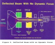
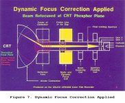
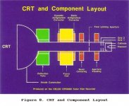
http://celco-nj.com/SID_Paper01.htm
ELECTRON OPTICAL TECHNIQUES FOR AN ULTRA HIGH RESOLUTION COLOR FILM RECORDER
John M. Constantine, Jr.
CELCO / Yoke Designer
14 Industrial Avenue, Mahwah, New Jersey 07430
"Deflecting the Electron Beam
We are now ready to deflect the electron beam. To maintain a focused spot as it is deflected from CRT center towards the edge, it is necessary to reduce the strength of the focus field. This is due to the increase in path length from the focus coil to the flat plane of the CRT face and added focusing action of the deflection yoke fields on the beam. (See Figure 6.) "


Dynamic focusing.
I have seen this kind of complicated focusing/deflection system in computer monitors, somethimes very strange in design.
Last edited:
Yes, right. I can not say it better.There is only one current flowing in the wire. As current is a rate of electrons flowing per time unit, cannot be some electrons "running" at one rhythm and others to another rhythm. I know that velocities are mean values, actually some go faster than others, but all them create only one current in the wire.
But I prefer to use the word "gradient" instead of "velocity" to make it closer to generally accepted "slew rate", which (not always) correlates with "musicality" of the audio equipment.
Because Fe2O3 has higher permeability around 6...20 and therefore could affect high gradient signals (read "high-frequency components").Hello Alex.
You specify CrO2 tape......why specifically CrO2 tape and not other tape formulations ?.
Dan.
See for example:
https://www.jstage.jst.go.jp/article/isijinternational/50/10/50_10_1514/_pdf
3 days passed and still nobody here tries the "new" method.
(...deeply thinking...)
I think
it takes a great deal of courage - to wrap a VHS tape around a tinned copper wire.
You lazy fat cats audiophiles.
(just kidding with a friendly smile).
(...deeply thinking...)
I think
it takes a great deal of courage - to wrap a VHS tape around a tinned copper wire.
You lazy fat cats audiophiles.
(just kidding with a friendly smile).

Last edited:
I see you dump here a link to a paper that is totally irrelevant to audio:Because Fe2O3 has higher permeability around 6...20 and therefore could affect high gradient signals (read "high-frequency components").
See for example:
https://www.jstage.jst.go.jp/article/isijinternational/50/10/50_10_1514/_pdf
Micro wave in the frequency range between 0.2 and 13.5 GHz.
From randomly googling with Fe2O3 I presume.
1). Permeability is stable within wide range of frequencies. So the measurement of permeability at 200 MHz apply at 432 Hz too.I see you dump here a link to a paper that is totally irrelevant to audio:
Micro wave in the frequency range between 0.2 and 13.5 GHz.
From randomly googling with Fe2O3 I presume.
2). Forget about "frequencies". Complicated musical signal with number of modulated harmonics is equal to high-frequency high voltage signal with high gradient. There is a mathematical proof. It is called "Ageyev's theorem".
See details at
Digitalized music causing stress??
Last edited:
1)It is called "Ageyev's theorem".
Nothing seems to turn up, only in Russian I assume?
- Status
- Not open for further replies.
- Home
- Design & Build
- Parts
- Skin Effect in Wires.