Zen Mod,
I have a question about R23 and R25 in your Pumpkin schematic. The sum of their values is 8K2 which is available. There is no other component connected in between them. Why did you use two separate resistors instead of a single one?
RN60D8201FB14
RN60D8251FB14
I have a question about R23 and R25 in your Pumpkin schematic. The sum of their values is 8K2 which is available. There is no other component connected in between them. Why did you use two separate resistors instead of a single one?
RN60D8201FB14
RN60D8251FB14
they're here to eat some voltage , keeping Q11 happy warm , not screeching hot
two of them - dissipation reasons
sum value not critical , +/-10%
two of them - dissipation reasons
sum value not critical , +/-10%
final schematics
Hi Zen Mod,
About 10 years ago I got Pumpkin and Shunty printed boards from you, with many important parts, like paired semiconductors, and I just started to collect all necessary parts, and solder.
Because boards interleaving paper used by you looks very archival (newspaper dated: UTORAK, 25 AVGUST 2009), I am affraid I do not have an actual schematic diagrams. I tried to find on this Forum, I see so many pages, maybe I am to lazy 😉 or/and to old 😕...So I will appreciate very very much for final version of Shunty and Pumpkin schematics.
Best Regards,
Andrzej
Last edited:
 cook book in my sig
Hi Zen Mod,
About 10 years ago I got Pumpkin and Shunty printed boards from you, with many important parts, like paired semiconductors, and I just started to collect all necessary parts, and solder.
Almost 10 years my two f4 monoblocks they were connected to DAC output only. Now are connected to Pumpkin. All sounds very clean, and strong like a volcano...
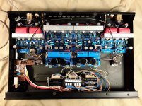
So my Pumpkin is almost ready, needs some mechanical machining, most important are ventilation holes - I plan to do it during summer.
Pumpkin & Shunty modules are in housing of an old damaged Cambridge Audio DAC I bought second hand in 1999; I use all 3 original DAC transformers (3x(2x15VAC))= 2x45VAC.
Gain adjustment is made on two 2x12 rotary switches, with 1% resistor ladders. Thanks to this I know that if I turn each knob with the same number of clicks, I have the same loudness in both channels (Nelson Pass perfect symetry effect). These switches were originally installed in my Son Of Zen (I described it in the years 1998-1999 somewhere on the pages of Mr. Nelson Pass), then transferred to f4 and now transferred to Pumpkin.
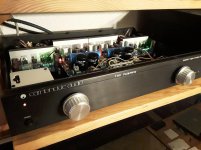
An interesting fact is that both silver knobs come from the middle 1970s, when the 'Elisabeth Stereo' radio was produced in Poland under the Japanese license. I never had such a radio, but I managed to get knobs for DIY projects. Times were hard but I was young.
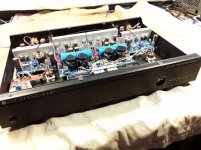
See attached pictures, I emphasize that this version is not yet finished, but plays beautifully. Zen Mod can honestly say: fugly, especially that in addition to the word 'Pumpkin' you can see and others ...
Zen Mod, thank you very much for fantastic project and helping me at start-up.
My Best Regards,
Andrzej
Attachments


should I finally work on Pumpkin's final iteration - one big pcb per channel , with everything on it - selector , shunts , gain stage with servo (so without caps in signal chain and no fussy setting procedure ) ?
Last edited:
should I finally work on Pumpkin's final iteration - one big pcb per channel , with everything on it - selector , shunts , gain stage with servo (so without caps in signal chain and no fussy setting procedure ) ?
Good idea, but I think one big pcb may be not as conveniet as two small pcb's.
I have following suggestions coming from my experience:
- instead of R24 270 Ohm use 100 Ohm + multiturn potentiometer 500 Ohm to have possibility to precise tuning 5mA Q11 CCS.
- green leds D1...D6 - old versions of 1V93 are difficult to find today, maybe a small mod for new generation of 2V8 green leds?
Kind Regards,
Andrzej
Yeah
One big pcb per channel would be great!
I have two more or less finished F4 laying arround and waiting for
exactly that 😉
Andrzej: Use 4 green Leds instead the 6
One big pcb per channel would be great!
I have two more or less finished F4 laying arround and waiting for
exactly that 😉
Andrzej: Use 4 green Leds instead the 6
Andrzej: Use 4 green Leds instead the 6
I do not plan to do it, maybe in the future; now I am tired and afraid that my pcb boards are tired too because the points and pins start to peel off...
There is one thing I would like to do: decrease gain to 5x instead 10x according documentation at the The Pumpkin & Shunty cookbook.pdf.
Best Regards,
Andrzej
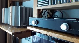
One photo more: Pumpkin & f4
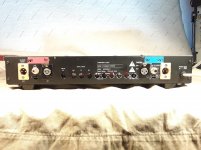
Due to the high temperature I could not close my Pumpkin casing, I decided to use forced air circulation. The dimensions of the device enabled the use of a tiny 40 mm fan. Unfortunately, its noise was clearly audible (supply 7-12 V DC, according to the fan manufacturer's data). I tried to reduce the rotation in different ways, using, among others, ideas with thermistors, but the results were not satisfactory.
Finally I went down with power from 12V to 3V6 DC using a 330 ohm series resistor. Finally, it got quiet, except that the fan did not want to spin when the preamplifier was turned on. And I found the simplest and the most effective solution: in parallel with the resistor, I used a 2200 μF capacitor, allowing the fan to 'start'. When the power is turned on, a 12V voltage appears on the fan, quickly drops to 3V6 as the capacitor charges.
Fan used: an old Revoltec - Air Guard 40 mm.
The described solution may be useful in devices in which not very intensive air exchange is necessary, while 'normally' powered fans generate irritating noises.
Last edited:
- Home
- Amplifiers
- Pass Labs
- Pumpkin Preamp - Perfect for F4