IXFH30N50P is the mosfets part number that are in the amp. are these the right one for this model?
Last edited:
Were any of those 3 leaky?
Yes.
It's odd that 3 were reading the same. They should be in two groups of 8 parallel FETs and all parallel FETs should have read the same.
Yes.
It's odd that 3 were reading the same. They should be in two groups of 8 parallel FETs and all parallel FETs should have read the same.
Clean the corrosion off. Had to read do it. They all read 0.no leaks I took all the output mosfets out. On the board itself. where the mosfet goes, source to gate I'm get .078 on all fet location. the drain,with the black lead for my scope to the amplifier negative input and the red lead to the drain pad on the board ,with amplifier power I am getting +108 on all drain pads fet on the side where the pre-amp board plugs into. On the other side where the rca inputs at I'm getting +18 on drain paid.
Last edited:
The low-side drain is connected to the speaker terminals. Do you have 18v on the speaker terminals?
What sort of problem did you have with corrosion?
Do you read -108 on the source and gate pads of the low-side FETs?
What sort of problem did you have with corrosion?
Do you read -108 on the source and gate pads of the low-side FETs?
Yes I have +18.36 volt at the terminals.
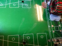
Surface corrosion around the fets pads. Greenish blue looking corrosion. Mainly on the side with the RCA inputs are at.
-109.8 on the source and gate low side fets that are on the speaker terminal side. But two that are the closest to the speaker terminals on the gate pad I'm getting -97
Surface corrosion around the fets pads. Greenish blue looking corrosion. Mainly on the side with the RCA inputs are at.
-109.8 on the source and gate low side fets that are on the speaker terminal side. But two that are the closest to the speaker terminals on the gate pad I'm getting -97
Last edited:
On the B+ input on the amp I havent used and current limiting. My power supply allows me to set the limit amperage by 5,10, then it's jumps to 25 as a select amp output. It pulls bout 28 amps for a brief second powering on after that the amp ilde at 1.8amps
The readings you've posted seem like there is damage to the board. I want to see what the voltage drop across certain points at a higher current than a multimeter can drive through the circuit. Do you have something like a 100w, 2 ohm resistor that you can use for current limiting?
When I set the power supply to 5 amps limit output the amp goes into protect both protect and power light come on.
The readings you've posted seem like there is damage to the board. I want to see what the voltage drop across certain points at a higher current than a multimeter can drive through the circuit. Do you have something like a 100w, 2 ohm resistor that you can use for current limiting?
Yes I do
OK. It will probably be needed later.
At this point, you need to find where the 18v is coming from. Place the black probe on the main ground and rub the red probe around on the board near the drain pads of the low-side FETs and the source pads of the high-side FETs (these are connected to the output terminals). Do you see any leakage of voltage that shouldn't be there?
Post a good quality photo of the corroded area.
I remove the heatsink to get a better look still tracking down the pads.when I took out the heatsink part of the green layer of the board was stuck to it and corrosion around this area when I try to clean with a toothbrush it just flakes away. Also some of the thermal paste was connecting three of the pins together on the high side fets
Attachments
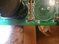
Ok resistor r4082 or r4087 I can not tell Wich number is reference for the component location. But it got so hot it unsolder from the board but I also trace my voltage back to this resistor. One side of the pad that the resistor was solder to shows 18 volt the other side shows -2.838 just for a brief second then it goes away. On the low fets pad I'm getting -2.838 volts just for brief second then it goes away to zero. I took the resistor out now the pad reads +133 where the resistor was at.
Attachments
Powering up the amp without heatsinking for the regulators (at least) risks blowing the regulators. In some similar amps, the regulators can fail within seconds, destroying anything that's powered by them.
It depends on which regulator failed and what was connected to the amp (preamp board, specifically) at the time.
Nothing was connected .no pre-amp bored. All output fets are out. Only thing that was connected was my scope and the pins 5 6/7 Wich all couplers are out too.
- Home
- General Interest
- Car Audio
- Mtx ta92001 distorted output.