Interesting point!using one hum-buck OT in another circuit is not sure to get benefit.
I think these days the competition in the hum-killing department is a power MOSFET and a few passive components, wired as a linear voltage regulator.
-Gnobuddy
All I can say is this ECL82 amp with the hum bucking winding activated is showing 10mV hum peak to peak at the speaker against 10V pp signal at clipping. The hum has gone down so far I was able to reduce the primary PSU cap from 44uF to 22uF and use the liberated cap to decouple the screen grid.
Works for me 🙂
Pete
Works for me 🙂
Pete
I believe the hum-bucking has to be balanced against the values of the caps and the PSRR of the circuit, so just using one hum-buck OT in another circuit is not sure to get benefit.
The theory behind this form of hum cancellation relies on low impedances of especially the 2nd filter cap and, to some minor extend, the final's cathode decoupling cap wrt the hum frequency. It won't work correctly if these caps are degradaded or if they're too low in value.
Best regards!
OK, lets try a link to a sound sample....
This the single valve amp through my 12 inch Celestion Greenback recorded close miked with a SM57 style mic. The amp is set to max volume so you can get some idea of how low the hum is...
I changed pickups a couple of times so you get a feel for the amp with different signals. Listen carefully at the end where I let the note die away and you can tell the amp is certainly not HiFi clean however.
ECL82 Clean by Pete Hanson | Free Listening on SoundCloud
Last edited:
OK, that link seemed to work, so here is another sound sample. Same amp and setup, but with the my feedback switch set to include a pair of LEDs in the loop to create early bend.
I tweaked the FET gain last night so I suspect the preamp is now a bit over enthusiastic when it comes to driving the main amp...
Regarding the recording: No tricks here. I used a little bit of EQ (-6dB ay 300Hz) because the crunch recordings sounded a bit middly. Also the speaker is in the corner of the room so there's a bit of unwanted bass loading. I have a small amount of reverb added because I don't like dry amps. Apart from that, no compression or overdrive plug ins or sneaky tricks...
ECL82 Crunch1 by Pete Hanson | Free Listening on SoundCloud
Last edited:
... And finally a link to the sound sample of the amp with the feedback mostly disabled. This gets dirty and muddy very quickly. Not so much to my taste..
Note, in all these sound samples, I don't use a pick, and play finger style. Maybe using a pick would add more attack.
ECL82 Full Crunch by Pete Hanson | Free Listening on SoundCloud
Note, in all these sound samples, I don't use a pick, and play finger style. Maybe using a pick would add more attack.
ECL82 Full Crunch by Pete Hanson | Free Listening on SoundCloud
Last edited:
Pete, just to clarify, I wasn't in any way disparaging the 1950's hum-cancelling technique. I think it was ingenious, simple, and clearly, it was effective as well.The hum has gone down so far I was able to reduce the primary PSU cap from 44uF to 22uF and use the liberated cap to decouple the screen grid.
My comment was simply that if you were to ask an audio engineer (or DIY builder) to solve the same problem of excessive 100 Hz supply ripple today, it would probably be done with other tools, some of which didn't exist in the 1950s.
Thanks for the sound clips, as well!
-Gnobuddy
Absolutely... A modern method would certainly be better engineered. I'm just surprised how well this weird trick seems to work. You do need to trim the hum balance resistor to make it function correctly. And it doesn't cancel all the hum but it certainly has resulted my quietest class A guitar amp, rather to my surprise 🙂
Pete
Pete
Btw, when you power on an old radio with this hum compensation and a selenium rectifier (not a vacuum diode!), you first hear significant hum in it's speaker, which decreases when the final's cathode warms up, i.e. when hum balancing occurs.
Best regards!
Best regards!
Yes I remember... I grew up with valve radios. The warmth, the smell, the wait, the hum... Lovely.
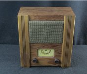
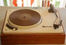
This wartime civilian wireless set formed the basis of my first diy record player. The RF section had long ceased to function, but the audio amplifier performed remarkably well when fed from the crystal cartridge in my Garrard SRP 10 turntable. This was my introduction to the world of diy audio as a young teenager. Happy days! 🙂
Wartime Civilian Receiver
Wartime Civilian Receiver
Attachments
Fantastic!
As a kid I was given broken valve radios by aunts and uncles, with the comment "if you can't fix it, you can keep it" Needless to say I couldn't fix them.
Alas I wasn't interested in valves way back then, so I dismantled them for their lesser components, and the rest went in the bin.
I did "help" my dad build a Heathkit S99 stereo amp (this would be about 1966). Looking at the circuit now, its quite sophisticated, push pull ECL86 with ultra linear transformer taps, proper Baxandall tone controls, plus various "scratch filters". From that start a whole career was born..
Last edited:
Oh dear.
I just won a bag of five mixed vintage radio output transformers. No idea what ratios they are - but hey, we live on the edge here. This means up to five new valve amp projects. For obvious reasons I'm having them delivered to work, not home 🙂
Meanwhile, the almost single valve amp has reached a development plateau. I'm getting together a suitable second hand speaker and box so the circuit can be re-engineered in a a proper enclosure. When I have that sorted I will start a new thread detailing the final circuit, and include some sound clips.
It now sounds very much how I like my amps, and it was the extra gain from the FET input stage that made the difference.
Pete
PS. My colleague at work brought in his 1976 Vox AC50 head. This is apparently the tag strip wired re-issue of the early 1960s design, and it is very nicely made inside.
We plan to gently refurbish it.
Last edited:
Care to share any tips on your amp tweaking / development process? This is the part that seems to take me forever, sometimes until I give up in frustration. I'd love to hear how you do it.Meanwhile, the almost single valve amp has reached a development plateau.
Saved by the FET!it was the extra gain from the FET input stage that made the difference.
Interestingly, it turns out that vacuum triodes are actually square-law devices, like JFETs. The fabled "three-halves" law doesn't seem to apply to actual valve geometries: https://dspace.mit.edu/bitstream/handle/1721.1/52044/RLE_QPR_045_I.pdf?sequence=1
So there is no need to feel any lingering pangs over the crime of putting an FET in the otherwise vacuum-state signal path of your amp. 🙂
-Gnobuddy
Care to share any tips on your amp tweaking / development process? This is the part that seems to take me forever, sometimes until I give up in frustration. I'd love to hear how you do it.
.......
-Gnobuddy
Yes, certainly... First let me relate a conversation I had last year with my guitar mad teenage grandson.
So did you customise your guitar grandad?
Yes, I rewired it and added some extra pickup combinations. Furthermore I customised my Fender valve amp as well.
Cool! I want to customise my amp. How long did it take?
Well, I did it in little stages and checked the results each time. So it took me about a month.
Wow! I want to do that. Is it easy?
Hmm, I guess you need to know what you're doing with analogue circuits to tweak an amp. But it can be learned.
Fantastic! How long does it take to learn analogue circuits so you can mod an amp?
About forty five years...
🙂
But seriously, I do my builds and my tweaks in small increments. I use Analogue scope, Ear and the Spectrum Analyser on my USB scope.
Firstly the one valve amp got it's heater wired, and the HT supply assembled with a bleed resistor, then I applied power just long enough to check the HT voltage, then check the heaters light. Provided it doesn't catch fire I can move on.
Then I switch to scope, signal generator and dummy load. My signal gen is a bit rough and ready (home made of course) but it's good enough to chase a signal through the pre-amp and main amp sections and measure the output power.
In this case I realised the power transformer was under rated for the task, so I set about buying a larger one.
Scope and dummy load is where I go looking for oscillation, and then trying to find the cause. (Missing grid stopper resistor, high impedance signal wires too close together etc)
At this stage I switch to loudspeaker output and guitar input. This is when I listen for the tonality, hum and noise. My method is to only change one thing at a time, and I also keep my schematic up to date. That was where I started adding smoothing to clean up the hum. Much later I revisited the transformer and rewired it to try the neat hum cancelling trick discussed back up the thread. I was deeply impressed with how well that worked BTW.
Finally, I move on to the polishing stage. With reasonable output power and with the hum nice and low and the tone stack values stolen from another amp, I find there isn't enough gain in the amp - so I figure the most valve like solution is a FET front end. I've worked with FETs before so I had an idea of what might work. At this stage I can see that the FET bias can bring a load of 2nd harmonic distortion if you need it. So finally I switch to a more sophisticated measurement method.
Out goes the analogue scope, in comes the USB scope with FFT spectrum analyser. Also my nasty signal generator goes. I use a sine generator on my phone. That proves to be quite clean, but not clean enough. It has some 3rd harmonic at -30dB which I don't need. So I pass the phone headphone output through a "twin T" R-C filter where the notch takes out the unwanted harmonic leaving a really clean 440Hz test tone.
Now I can measure the harmonic content at different points in the amp and observe the effect of bias changes. Every now and then I add a speaker and guitar to see how it sounds.
Finally, it is complete, finished, perfect, and I leave it alone and just use it.
OK, that last bit is a lie.
Pete
Last edited:
... And I was so impressed by the sound of the FET front end I added a similar circuit to my so-called "finished" 6V6 amp.
The chassis has two guitar inputs, one is now high gain courtesy of a little PCB with a FET on it. I had to do some rather inventive wiring using the jack switching contacts to get the FET in circuit through one jack, but not in circuit through the other, and the amp silent with nothing plugged in.
The sneaky trick I used in both cases was powering the FET amp (at say 9v DC) from the pentode cathode resistor which has around 15v DC on it. As long as you don't take too much current you get free pre-amp power 🙂
Interestingly, it turns out that vacuum triodes are actually square-law devices, like JFETs. The fabled "three-halves" law doesn't seem to apply to actual valve geometries: https://dspace.mit.edu/bitstream/handle/1721.1/52044/RLE_QPR_045_I.pdf?sequence=1
So there is no need to feel any lingering pangs over the crime of putting an FET in the otherwise vacuum-state signal path of your amp. 🙂
-Gnobuddy
Woo - that was a dense read...
Eons ago I worked for the UK Atomic Energy as a junior in plasma physics research - so I should know something about electron dynamics.. Alas I forgot all I ever knew from those heady days
JFETs are not vacuum triodes.
JFETs have a built-in voltage Vto (turnoff voltage) which does not vary with drain voltage. In a vacuum triode "Vto" is a consistent fraction Mu of the plate voltage. This causes internal NFB; or we can say that the Mu of a JFET is infinite (too high to matter in practice) thus no NFB.
I also have doubts about those straight-line plots.
BTW, this does all come out of "3/2", looking at it different ways. (The paper points out a mistake made over a decade ago.)
But I have no qualm about using JFETs as music amplifiers.
Thanks for sharing some of your approach!
I built my first circuit - a crystal radio using a germanium diode, built with a soldering iron borrowed from my big brother - when I was around eight years old, maybe a little younger. From then on, I was constantly studying and building any kind of circuit that made any kind of sound. I started young and didn't stop until grad school made me too busy to continue, so the years of analog experience came sooner than most people would expect. 🙂
But valve guitar amps are an entirely different type of creature, and I've only been tinkering with those for a few years. So I still have a lot to learn about the weird world of intentional nonlinearities, sliding bias, blocking distortion, speakers that beam midrange like a searchlight and produce negligible output above 6 kHz, speaker "enclosures" that aren't actually enclosures but just baffles, et cetera!
Lately I've been tempted to trade in a valve amp I never use (it's too loud and too clean) for a Boss Katana 50 - a very good-sounding solid-state amp that is so complex internally that I will actually just "leave it alone and just use it". Maybe then I'd spend more time working on that modified natural minor scale with a "blue note" sprinkled in, instead of wondering if that $20 8" "full range" paging / P.A. speaker would work as a guitar speaker in my next build...
-Gnobuddy
This is the part that can drive me bonkers. I usually don't have much trouble getting acceptable clean tones. But getting good overdrive tone seems to be much trickier. Sometimes the tone changes in unexpected ways, for example, adding a two-resistor fixed attenuator to cut the signal by a few decibels between two gain stages can dramatically change the overdriven sound of the amp....I listen for the tonality...
I built my first circuit - a crystal radio using a germanium diode, built with a soldering iron borrowed from my big brother - when I was around eight years old, maybe a little younger. From then on, I was constantly studying and building any kind of circuit that made any kind of sound. I started young and didn't stop until grad school made me too busy to continue, so the years of analog experience came sooner than most people would expect. 🙂
But valve guitar amps are an entirely different type of creature, and I've only been tinkering with those for a few years. So I still have a lot to learn about the weird world of intentional nonlinearities, sliding bias, blocking distortion, speakers that beam midrange like a searchlight and produce negligible output above 6 kHz, speaker "enclosures" that aren't actually enclosures but just baffles, et cetera!
What do you look for in your THD spectra? Do you have rules of thumb (such as, say, "at least 5% second harmonic distortion at a signal level 6 dB before clipping in this stage"), or do you wing it?Now I can measure the harmonic content at different points in the amp and observe the effect of bias changes. Every now and then I add a speaker and guitar to see how it sounds.
Sure. Don't we all. 😀Finally, it is complete, finished, perfect, and I leave it alone and just use it.
Lately I've been tempted to trade in a valve amp I never use (it's too loud and too clean) for a Boss Katana 50 - a very good-sounding solid-state amp that is so complex internally that I will actually just "leave it alone and just use it". Maybe then I'd spend more time working on that modified natural minor scale with a "blue note" sprinkled in, instead of wondering if that $20 8" "full range" paging / P.A. speaker would work as a guitar speaker in my next build...
-Gnobuddy
Oh, I feel your pain... Getting clean tones is relatively easy. Getting rid of hum is more difficult and takes longer. Hiss is not easy to remove, I suspect I would try changing a valve for that...
I made a FET distortion pedal and scrapped it due to what I imagine was shot noise. That was disappointing.
However, getting that sublime overdrive sound is extremely difficult. You know it when you hear it. I have used asymmetric diode soft clipping in the preamp before and that sounds ok if you play gently. Kind of bedroom level blues club sound. However if you push it, the diode trick sounds fake.
What does work for me is LED soft clipping in the power amp feedback path. This only operates at higher powers but it can add a touch of early crunch to the sound before the pentode starts to clip.
I think the holy grail is to get all the amp stages to clip and contribute. This makes for a progressive crunch sound, but I can't see how you achieve this without high levels of sound...
I can see it starts with driving the first valve towards clipping. And that for me requires extra (FET) gain up front which is also capable of clipping. Then I need an attenuator to reduce the signal to the right level for the next valve.
Trial and mostly error
Last edited:
- Home
- Live Sound
- Instruments and Amps
- Newbie: Hi there and a ECL86 question