You're drawing too much power, probably a short somewhere. If you disconnect the phono stage and the resistors stay cool, you've hooked it up wrong. Check that the +, - and GND connections are correct.
That seems to be the case, the PCB didn't have the power +,-,ground labeled. Seems I had it totally wrong.
Without the preamp connected resistors stay cool.
I am getting some odd readings though.
I get +15.15V which is correct.
But I am getting -24.9V the other way.
What could be doing that? That can't be right.
Without the preamp connected resistors stay cool.
I am getting some odd readings though.
I get +15.15V which is correct.
But I am getting -24.9V the other way.
What could be doing that? That can't be right.
Don't know the PSU (pictures are no longer available). If it's a LM317/LM337-based PSU, check that you have the right regulator in the correct place and that the orientation is right. Also check the resistors that set the voltage.
Apart from that, reflow every single solder joint and make sure they're all soldered. Check that all compontents are in the right place with the correct orientation and value.
24.9V seems very high. Are you sure you're measuring correctly?
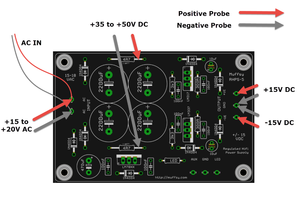
If it's anything like the Muffsy PSU, the readings should be like this:
Apart from that, reflow every single solder joint and make sure they're all soldered. Check that all compontents are in the right place with the correct orientation and value.
24.9V seems very high. Are you sure you're measuring correctly?
If it's anything like the Muffsy PSU, the readings should be like this:
Last edited:
Thanks for your help!
His PSU is more or less the same as yours, I think he even based it on one of your earlier Muffsy designs.
Yup I am measuring correctly. AC in reads 19.2v, the reading at the resistors is 50 V, the reading at V+ is basically +15, all normal–it is V- that is weird at -24.9. My 9-volt battery supply reads totally properly too, so measuring seems fine.
I'm guessing the IC is goofy or the resistors are wonky. All resistors measure at their proper values, but it feels like they aren't setting the voltage properly somehow.
So now I am going to reflow the solder later tonight and see what happens.
Maybe Muddyboots can verify if the PSU is working or not?
All information about it seems to be lost, so it's not easy helping you. You do get exactly half the rail-to-rail voltage, which would indicate either a faulty LM337 (check that it really is an LM337!), or a short somewhere.
Assuming the PSU is supposed to be working, the only other thing I can think of is that the protective diode on the LM337 is oriented the wrong way. I don't know if this PSU has a protective diode, and you've already verified that all components, values and orientation...
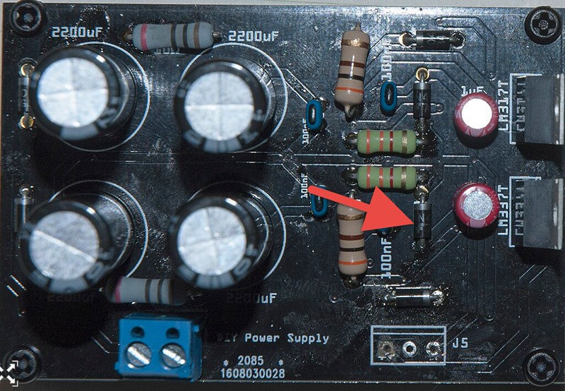
Here is a bad photo of the board, kinda dirty, didn't bother cleaning after I reflowed the solder tonight.
It didn't help, now V- reads -25. It is a LM337 (Fairchild, got it from Mouser)
According to screen printing on PSU everything lined up properly. All resistors measure correctly. Maybe a mistake on printing and something is reversed (I wonder about the diode by the green resistor by the LM337, without the schematic I can't quite tell), maybe IC is bad.
Hmm… I might just call it and just order one of yours just to keep life easy.
Attachments
I'm pretty sure this diode should be rotated 180 degrees:
That's quite a messy layout imho. It looks to me as if it's using both a ground fill and ground tracks. Try it out. If your phono pre hums, you'll know why.
That's quite a messy layout imho. It looks to me as if it's using both a ground fill and ground tracks. Try it out. If your phono pre hums, you'll know why.
Hey FantasicoGrande,
I apologise that the PSU isn't working properly. Unfortunately I lost the schematic for it, but it was based on the Muffsy PSU. I simply tried to allow for some more room for different components. Like I mentioned in my original post, it was an untested design and I did not get a chance to assemble one myself.
Again, I apologise for the trouble.
muddyboots, FantasticoGrande:
Sorry about the harsh words, the PSU has all the potential of working. Stuff usually does at this level, even with a layout that isn't optimal. The op amps' bypass caps and their high noise rejection should take care of that.
Do you remember at all if the voltage regulator protection diodes are the horizontal or vertical ones? If they're the vertical ones, my suggestion above is correct.
If it's difficult to rotate that diode, all four of them can be omitted (just take care not to connect the full 30V output to anything (i.e. connecting something to the + and - terminals, and not the GND, which will give you the full 15 + 15 volts).
thanks both of you for all your help
muddy, no worries, I knew this was an untested design going in
that being said I tried some things:
I reversed that diode, nothing changed on measurements
then I took all four diodes out, nothing changed on measurements
I basically have given up on this guy for now,
I'm going to order one of yours skrodahl.
In the meanwhile I'm going to run the pre on batteries, sounds really good so far that way.
Dragging up an old thread ...
I am considering powering a board with a Meanwell AC~DC SMPS (120VAC input; +/- 15VDC output). Ripple and Noise seems to be low enough, freq is 100 KHz.
Anyone see any issues with this plan? It is possible to add filtering of the output of the SMPS but I am not convinced it is necessary.
Meanwell 2515 25W SMPS
Mouser #: 709-PD2515
I say try it out, can't really argue on the price.
I'm using one of these with similar ripple, and similar price as well:
WRD241212YS-2W pdf, WRD241212YS-2W description, WRD241212YS-2W datasheets, WRD241212YS-2W view ::: ALLDATASHEET :::
I'm using one of these with similar ripple, and similar price as well:
WRD241212YS-2W pdf, WRD241212YS-2W description, WRD241212YS-2W datasheets, WRD241212YS-2W view ::: ALLDATASHEET :::
Is there one phono board available to purchase?
You can buy boards at the link in skrodahl's sig although the current Muffsy boards are different than the ones referred to in this thread.
If you really want one of the boards referred to in this thread, PM me. I have a few.
Anybody know where I can buy the board? Its discontinued at their website
I have two I would be glad to sell. Shoot me a private message.
PS Audio sells the board at cost, to US customers:
DIY CNC Phono board | PS Audio
Disclaimer:
I published the design as open source. I am not responsible for, nor do I get any money from, PS Audio selling the boards.
DIY CNC Phono board | PS Audio
Disclaimer:
I published the design as open source. I am not responsible for, nor do I get any money from, PS Audio selling the boards.
I have two I would be glad to sell. Shoot me a private message.
I sent you the money and you never sent anything. Are you that hard up for money you have to steal $10 from forum members?
PS Audio sells the board at cost, to US customers:
DIY CNC Phono board | PS Audio
Disclaimer:
I published the design as open source. I am not responsible for, nor do I get any money from, PS Audio selling the boards.
They don't have these anymore. I went ahead and ran some boards at seeed (both the phono and the PSU).
- Home
- Group Buys
- Make Your Own Muffsy Phono Stage Group Buy