Hi, I'm new around here. I don’t speak English and I have to say that I use google traslate to write and read in this forum. I hope this isn’t a problem. I have to say that, too, that I’m not an expert in the design of loudspeakers so maybe I can say things that are not right or make mistakes.
The reason for this thread is to comment my experience with ESS AMT tweeters and, at the same time, request help to optimize its use. I have been developing a project for "semi-DIY" loudspeakers, the ATS loudspeakers from Troels Gravensen Jenzen-ATS This project is already closed in its original design. I have made some improvements to the filter and wiring components of the loudspeakers with very good results for my taste. Especially use Duelund components for some parts of the filter (cap for high frequencies, resistors and cable for high and medium frequencies).
However, for a long time I have had an interest in the ESS AMT and the desire to be able to evaluate its performance. Because the design of the ATS has three separate enclosures and the external crossover it was relatively easy to test. I thought that with the cutoff at 2300Hz and a 2nd order filter, it might be possible to try to integrate the ESS into the ATS. Adjusting the input resistance to the desired level. The impedance of the ESS is 4 omh (like the Scan Speak of the ATS) with a simple impedance curve. I also added an RLC circuit to finish flattening the impedance.
The result has been somewhat contradictory for me. It is true that the sound of the ESS is extremely revealing and detailed with a great ability to do all this naturally.
However, in some recordings the "salivation" of the voices is very marked. I think this point is collected between 5 to 7 khz. In the first tests without RLC circuit the problem was greater. With the circuit RlC and with some foam on the sides, the problem improved but did not disappear.
I have read that other people have had this problem. There is no solution? Because the rest of the ESS sound is very good.
regards
Attachments
Toni, I think the problem you are hearing is caused by diffraction, and you may find it varies with the listening angle. There is a discontinuity (step) in the magnet pole pieces at the plastic cover on the magnets.
Smoothing this step with something like car body filler may help, although you would need to be careful not to damage the membrane by two mechanisms.
1 The catalyst used to cure the filler may emit fumes that are not good for the membrane.
2 The dust caused by sanding/smoothing the filler needs to be kept out of the membrane.
Maybe you could experiment by adding some plasticine to see if this is the cause of what you are hearing.
Keith
Hi Toni!"However, in some recordings the "salivation" of the voices is very marked."
I think Google translator has let you down there! The correct translation must be "sibilance" 🙂
I have noticed this too. The AMT can be very bright. I use an active crossover and have just a touch of high shelf dialed in to correct that.
The ESS HEIL AMT has a frequency response that rises at approximately 6dB per octave from low to high frequencies. A parallel network consisting of a 65 microhenry inductor with a 22 Ohm resistor connected in series with the AMT is all that is required to eliminate this foible.
A crossover at a lower frequency, say 1.2 kHz makes it easier to integrate the speakers in the system which each other as you are then dealing with longer wavelengths.
Attenuation of the AMT with an L pad is often required to adjust its' high sensitivity to match the other speakers.
A crossover at a lower frequency, say 1.2 kHz makes it easier to integrate the speakers in the system which each other as you are then dealing with longer wavelengths.
Attenuation of the AMT with an L pad is often required to adjust its' high sensitivity to match the other speakers.
Last edited:
The ESS HEIL AMT has a frequency response that rises at approximately 6dB per octave from low to high frequencies. A parallel network consisting of a 65 microhenry inductor with a 22 Ohm resistor connected in series with the AMT is all that is required to eliminate this foible.
A crossover at a lower frequency, say 1.2 kHz makes it easier to integrate the speakers in the system which each other as you are then dealing with longer wavelengths.
Attenuation of the AMT with an L pad is often required to adjust its' high sensitivity to match the other speakers.
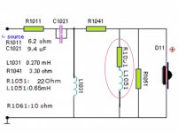
Hi, thank you for you answer. Currently I use a crossover of 2on ordre with a cut to 2.3khz (the original of the ATS) I have only measured the first resistance (much larger than the original) and the LCR network (the same used for some ESS in a project I located on the internet). I attached a photo of the current crossover scheme. I have also made a scheme with the solution that you propose. I understood correctly? Is the scheme correct?
Attachments
thanks for your reply.Toni, I think the problem you are hearing is caused by diffraction, and you may find it varies with the listening angle. There is a discontinuity (step) in the magnet pole pieces at the plastic cover on the magnets.
Smoothing this step with something like car body filler may help, although you would need to be careful not to damage the membrane by two mechanisms.
1 The catalyst used to cure the filler may emit fumes that are not good for the membrane.
2 The dust caused by sanding/smoothing the filler needs to be kept out of the membrane.
Maybe you could experiment by adding some plasticine to see if this is the cause of what you are hearing.
Keith
Regards
Hi Toni!
I think Google translator has let you down there! The correct translation must be "sibilance" 🙂
yes, you are right, jejej
I have noticed this too. The AMT can be very bright. I use an active crossover and have just a touch of high shelf dialed in to correct that.
Unfortunately I use a passive crosorver
Regards
They have a rising response with a peak at 5k. I use a passive notch filter to help flatten the response.
Rob🙂
Rob🙂
Hi, can you share the values of the RLC circuit?They have a rising response with a peak at 5k. I use a passive notch filter to help flatten the response.
Rob🙂
Regards
Sure but if you are going passive the notch would need to be tweaked depending on where you are crossing over and parts values and slope. Here is a link to a thread I have running. I have a notch for an active set-up that would not have to be if you are OK with the curve. It sounds good but I have only had a chance to do a mono evaluation.
Rob 🙂
Heil with a JBL woofer - Page 2
Rob 🙂
Heil with a JBL woofer - Page 2
The crossover circuit that you have drawn with the red circled components is not correct. You have shown a series resistor and inductor combination that is in parallel with the treble speaker. What I do is fit a parallel resistor and inductor in series with the treble speaker. Incidentally the inductor value is 0.065 milli Henries. This network should be fitted between the 'L' pad and the tweeter and preceded by the 2nd order crossover network. The corrected ESS HEIL AMT has an average sensitivity of 95 dB from 3 kHz upwards for a 2.83 volt signal at 1 m on axis. Your crossover and 'L' pad may require some adjustments of component values to take into account the impedance of the AMT in the crossover frequency region.Hi, thank you for you answer. Currently I use a crossover of 2on ordre with a cut to 2.3khz (the original of the ATS) I have only measured the first resistance (much larger than the original) and the LCR network (the same used for some ESS in a project I located on the internet). I attached a photo of the current crossover scheme. I have also made a scheme with the solution that you propose. I understood correctly? Is the scheme correct?
Sure but if you are going passive the notch would need to be tweaked depending on where you are crossing over and parts values and slope. Here is a link to a thread I have running. I have a notch for an active set-up that would not have to be if you are OK with the curve. It sounds good but I have only had a chance to do a mono evaluation.
Rob 🙂
Heil with a JBL woofer - Page 2
Ok, thanks
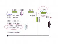
The crossover circuit that you have drawn with the red circled components is not correct. You have shown a series resistor and inductor combination that is in parallel with the treble speaker. What I do is fit a parallel resistor and inductor in series with the treble speaker. Incidentally the inductor value is 0.065 milli Henries. This network should be fitted between the 'L' pad and the tweeter and preceded by the 2nd order crossover network. The corrected ESS HEIL AMT has an average sensitivity of 95 dB from 3 kHz upwards for a 2.83 volt signal at 1 m on axis. Your crossover and 'L' pad may require some adjustments of component values to take into account the impedance of the AMT in the crossover frequency region.
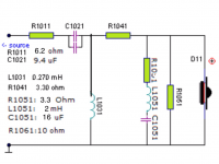
OK thanks. I try to understand. second chances Is this scheme correct? Thanks for the help.
Attachments
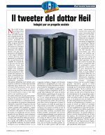
I use this italian review for take de notch circuit. The ESS in my ATS.
Attachments
-
 7C615119-301C-4C6D-9463-F1D76B55993E.jpg977.3 KB · Views: 672
 -
 6E6D5384-D04E-4C95-B5B9-C61BCAF0D759.jpeg836 KB · Views: 1,136
 -
 3C968F5F-C4AE-4110-98EC-B480015C1771.jpeg906.8 KB · Views: 1,011
 -
 CF1B6394-B6A1-4A2B-92C0-89AFF2A82162.jpg610 KB · Views: 986
 -
 BA4105FB-4E6B-4308-8F0B-A27EF45350AA.jpeg927.5 KB · Views: 1,347
Hello, in the attached article some modifications are exposed to improve the response of the ESS. One of the possibilities that is exposed is that it would be positive that the interior of the ESS chassis was filled with absorbent material. I have thought that it is possible to introduce cotton or other absorbent material through the holes for the screws but I am not sure that this will work. Has anyone come to perform this experiment?
Attachments
Toni G the plastic case is damped sufficiently by the clamp , pad and bolts that are used to hold the AMT to the top of a speaker enclosure. The simplest way to avoid any air leakage problem or vibration of the diaphragm frame assembly within the magnet housing , is to apply what is called a gasketing compound of the anaerobic adhesive variety, to the edges of the long sides frame before sliding it into the slots. The quantity used should only be about the size of a match head applied to each side. The compound is a gel that remains flexible but resists vibration.
I am not sure if you are using the latest version of the ESS HEIL AMTs or at least have units with the latest soft mylar diaphragms fitted.
I am not sure if you are using the latest version of the ESS HEIL AMTs or at least have units with the latest soft mylar diaphragms fitted.
Toni G the plastic case is damped sufficiently by the clamp , pad and bolts that are used to hold the AMT to the top of a speaker enclosure. The simplest way to avoid any air leakage problem or vibration of the diaphragm frame assembly within the magnet housing , is to apply what is called a gasketing compound of the anaerobic adhesive variety, to the edges of the long sides frame before sliding it into the slots. The quantity used should only be about the size of a match head applied to each side. The compound is a gel that remains flexible but resists vibration.
I am not sure if you are using the latest version of the ESS HEIL AMTs or at least have units with the latest soft mylar diaphragms fitted.
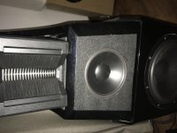
thank you very much for your help. My ESS was produced in July 2018. In the attached photo I mark the area that I understand that you say it is useful to seal. it is right? I also attach the photo with the circuit that you explained. it is right? I apologize for my comprehension problems with English
Attachments

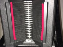
Your AMT is the latest type with the soft mylar diaphragm. The Audio Review article appears to show a version with a kapton diaphragm. The HI Fi-Selbstbau shows the first model of the AMT without disclosing whether the diaphragm has been changed. The clamping bolts and added base give it a macho look and the felt/velour covering hides the usual bare metal thin laminated pole pieces.
I do have problems with the value of the components in the crossover schematic that is supposed to be for a frequency of 2300 Hz. A Butterworth second order crossover would have values of 0.587 mH for the inductor and 8.156 mFd for the capacitor and this presumes that the L pad values are calculated to present a 6 ohm impedance to the network as well as providing attenuation to match the HEIL AMTs sensitivity to the mid-range speaker. The resistor ,R1011 is not something that I would use as I prefer to operate a crossover from a low impedance source. Presumably it is attempting a correction to match an 8 ohm or other design criteria.
What can you tell me about the midrange driver, i.e. Impedance, sensitivity and its' crossover network ?
Last edited:
- Home
- Loudspeakers
- Multi-Way
- ESS AMT tweeter. Help for correct use