Kevin amazes me with the work he has done. I couldn't do 10% of what he has achieved. Right now I am listening to a 1978 turntable with a 1978 cartridge on and I could just live with that forever!
But I would be very happy if we could conclude that all cartridges have the same resonant effect and the scale is related to cantilever design/mass and damping then try and characterise that.
But I would be very happy if we could conclude that all cartridges have the same resonant effect and the scale is related to cantilever design/mass and damping then try and characterise that.
I strongly prefer that the cantilever is a beam, and transverse vibrations propagate along it. It is then a transmission line. I did a lot of modelling of this a few years back and it hangs together given real material properties and dimensions.LD, In what direction is your feeling sending you ?
There's some evidence for it too, such as the second mode peak which is otherwise difficult to explain.
Well it is part of the equation for sure. Beams have group delay too: phase velocity depends on f.Just like the LCR and Resonance from the Cart are used to extend the FR.
In how far could this also be part of the equation ?
For sure. But mastering engineers built all this into the overall sound back in the day. Like artists have imperfect canvas and brushes, it's all included in the outcome😉With all this its like magic that an LP produces any music at all. 😀
LD
Yes it would be universal. Sticking a lump of mass at the end, or part way down, ie a generator, has a profound effect too. Everything bends in this life 😉If that is true (beam bending) then its a universal thing, not just MMs which would make me far more comfortable.
Exactly. It comes down to avoiding resonances that affect the audioband, which is common sense, if the rest of the cart is up to it. As can be.The graph I posted of LDs OM measurements (normal not super) is with no mech resonance correction. There is a slight HF rise consistent with an ultrasonic cantilever resonance but its small in the audioband. Looking at that, is there much to correct?
LD
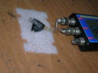
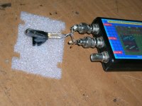
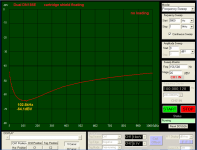
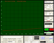
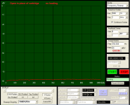
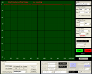
Preliminary tests on three cartridges Bill sent me.
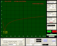
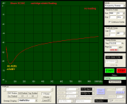
Voltage drop across the cartridge (forward transmission or A over R as Scott wrote)
The parallel resonance gives a dip, where with impedance sweeps there should be a peak.
George
Voltage drop across the cartridge (forward transmission or A over R as Scott wrote)
The parallel resonance gives a dip, where with impedance sweeps there should be a peak.
George
Attachments
-
 1 Ortofon Super OM10_shield floating-no loading_1MHz.PNG32.7 KB · Views: 196
 -
 9 Shure SC35C loaded.JPG659.4 KB · Views: 100
 -
 8 Dual DN185E no load.JPG653.5 KB · Views: 109
 -
 7 Super OM10 loaded.JPG679 KB · Views: 104
 -
 6 Shure SC35C_ shield floating-loaded_1MHz.PNG33.5 KB · Views: 89
 -
 5 Shure SC35C_ shield floating-no loading_1MHz.PNG32.1 KB · Views: 189
 -
 4 Dual DN185E_ shield floating-loaded_1MHz.PNG33.1 KB · Views: 186
 -
 3 Dual DN185E_ shield floating-no loaded_1MHz.PNG28.9 KB · Views: 189
 -
 2 Ortofon Super OM10_shield floating-loaded_1MHz.PNG33.4 KB · Views: 188
The test setup
George
George
Attachments
-
 7 open loaded-1MHz.PNG28.5 KB · Views: 92
 -
 6 open no loading_1MHz.PNG28.5 KB · Views: 96
 -
 5 short loaded-1MHz.PNG29 KB · Views: 97
 -
 4 short no loading-1MHz.PNG27.9 KB · Views: 89
 -
 3 short loaded.JPG944.5 KB · Views: 90
 -
 2 short no loading.JPG915.1 KB · Views: 101
 -
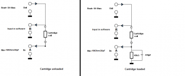 1 Test schematic.PNG15.7 KB · Views: 102
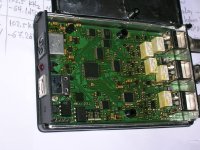
Hi Demian
“fastsampling.com”
They don’t list it anymore. USB Function Generator/Oscilloscope
I had bought it in 2009 for $205 through e-bay from a guy (rsabanovic, Pittsburgh) for working on tuners and radios (it’s not good for audio frequencies)
The hardware seems to be good. It is self contained. It uses the PC only for command entering and display.
The software is lousy, I wish I was an IT to poke in it. It doesn’t even work on some Win XP PCs. https://web.archive.org/web/2016042...m/Products/FunctionGenerator/DDSG2AManual.pdf
George
Attachments
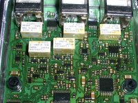
George- Who makes that little network analyzer?
FYI the Analog Discovery USB DAS has a network analyzer mode.
Yes it would be universal. Sticking a lump of mass at the end, or part way down, ie a generator, has a profound effect too. Everything bends in this life 😉
Stupid thought of the day, my new house has an unheated basement (55-60F) and my little lab system sounded a little off (bright) to me. If I could repeat the frequency sweeps in the garage with all the equipment stabilized at 40F or so would that help separate mechanical from electrical effects? My personal experience is that anything that depends on the properties of rubber or elastomers changes with temperature more dramatically than any electrical parameters.
My personal experience is that anything that depends on the properties of rubber
You didn't really say that did you?
Panasonic spent a lot of time developing dampers that didn't vary with temperature. Sadly it appears they just crumble over time instead.
Turntable environmental cabinets. My next tweek.
Turntable environmental cabinets. My next tweek.
Bill,Post 493 Cartridge dynamic behaviour
This was with LDs own Aurak as per his published circuit. There are some 'corrections' in that, but never simulated that.
Edit mechanical resonance in MMs I believe this is the version that was used for the measurement in #493
The image with the OM40 that you pointed to stops at 20kHz. I could produce many alternatives with the same FR up to 20kHz but differing quite a bit upwards.
I used the Aurak as originally published by LD, to stay as close as possible to what was being used for his recording.
The second Aurak stage is applying the Riaa 318usec and 3180usec time constants, I used a Laplace function for this.
With an anti Riaa signal these two stages produced a perfect flat FR.
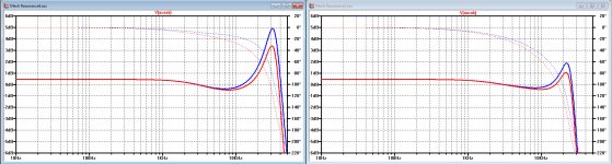
The first two images below are showing two examples where up to 20kHz FR is exactly the same to the original OM40 40 image, but beyond it can be anything as shown.
The images are showing the response with the 2k2/1n5 filter that's in LD's Aurak between the first and the second stage in red , and without this filter in blue.
It is obvious that this filter serves a purpose suppressing almost 0.9dB at 20kHz.
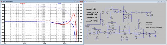
Comparing (Cart + Aurak) in red to a (Cart + 47K//150pF) in blue, both with the same Fres and Cart correction that was needed to replicate LD's OM40 image, gave the second image below.
From all variants I selected this version as the most likely.
Because there is not just a Cart resonance contributing to the FR, but obviously also a second mechanism, a correction afterwards is not that easily done with an anti resonance filter as van Maanen and van Raalte suggested.
It seems, looking at the Sims, that with virtual gnd "Aurakian" systems, one may encounter some HF problems. Also the dip at 10kHz may become deeper as with a 47k//150pF setup.
However, it would be nice to have a FR up to at least 50kHz, to be able to investigate thing more precisely or even better when also a 47K//150pF recording would be available.
Hans
Attachments
Hans.
Thank you for the analysis. We are back to how to get >20kHz in a test record 🙂.
Or playing existing 33rpm test records at 45 rpm ?
That only gets us a bit higher (27kHz). The ortofon record goes higher and I think Scott has some but are they calibrated? I suspect above 15k we are looking for the frequencies of the peaks rather than absolute values so we should be ok.
(aside I am an awful lot closer now to being able to contribute to this thread. Fingers crossed I can get the last dozen jobs done and start measuring).
(aside I am an awful lot closer now to being able to contribute to this thread. Fingers crossed I can get the last dozen jobs done and start measuring).
You didn't really say that did you?
😀


You made my day (night)
George
Scott has one test disk going to 50kHz flat freq.
If we donate him some op amp. ICs 😀 he may build an Aurak pre and tell us what he finds.
George
If we donate him some op amp. ICs 😀 he may build an Aurak pre and tell us what he finds.
George
Cut it slow, spin it quick. 😉Thank you for the analysis. We are back to how to get >20kHz in a test record 🙂.
I don't have test records that get far above the audioband…………..
LD
Hans.
Thank you for the analysis. We are back to how to get >20kHz in a test record 🙂.
The controller in one of my inexpensive Thorens Turntables is completely adjustable with a potentiometer -- that's how I got it to play 78's.
Donate? Scott normally donates 8-legs to us 🙂.
More seriously I wonder if we are not at the point where the design is proven enough that it's time to lay out a board and release the gerbers to anyone who wants a try. I believe everyone who contributed is happy with the open HW concept around it? Does of course depend if LD decides the negative R path is better 🙂.
More seriously I wonder if we are not at the point where the design is proven enough that it's time to lay out a board and release the gerbers to anyone who wants a try. I believe everyone who contributed is happy with the open HW concept around it? Does of course depend if LD decides the negative R path is better 🙂.
- Status
- Not open for further replies.
- Home
- Source & Line
- Analogue Source
- Cartridge dynamic behaviour