There is a mistype in the post:
I meant to say Drain to Gate capacitance, not drain to source.
Thanks to supernet for pointing it out.
...Small drain-source capacitors added to each MOSFET to shunt the inherent and variable drain-source capacitance. This eliminates all output stage parasitic oscillation due to MOSFET mismatch/interaction.
I meant to say Drain to Gate capacitance, not drain to source.
Thanks to supernet for pointing it out.
For EXICON mosfets is the mod necessary? I did not understand from your post 648.
Plz edit the schematic , thanks
Plz edit the schematic , thanks
Hi,
I am pondering about using these together with the V4 boards for an LX521 system (3xV4 and 2xV4H). It is required however that the amps used for this system all have the same voltage gain.
Is there a way to tune the V4 or the V4H in such a way that both have the same voltage gain? Reading the specs from posts 1 the gains are close but not the same.
Steef
Hi,
If you are using DSP then gain difference can be easily adjusted in DSP setting,if iam right there 1db gain difference between v4 and v4h
If you are using DSP then gain difference can be easily adjusted in DSP setting,if iam right there 1db gain difference between v4 and v4h
Hi
I was thinking about the ASP.4 from Hairballaudio so I need an analog solution.
Should a voltage divider with ratio 0.891251 do the job on the V4H inputs or the low channel output of the ASP.4? (Calculated from sengpielaudio.com/calculator-gainloss.htm); actually, if the voltage gains mentioned in the start posts are correct there actually is a reduced gain on the V4H of -0.548765 dB instead of -1 dB, so the divider should target a ratio of 0.938776.
Any resistor values I should aim for?
Steef
if you are planning for ASP and if have not build the amp modules best is to use V4h for all channels, for subs use +/-56V and+/- 45 V for rest of the modules and not worry about gain ( V4H MEASURES BETTER THAN V4)
if you need to adjust gain next best option is adjusting it in amp rather in ASP as small changes in gain structure in ASP( relative ) will have more effect in amp output voltages and if for some reason if you are upgrading amplifier in future you don't have to tinker ASP again
and it's better to reduce in V4H rather than increase V4 as our sensitivity of hearing in low frequency much less than in 1-5k ( much more forgiving)
shaan will be best person to advice on reducing gain
Last edited:
Silver mica rev 1
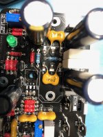
FWIW, I just completed my V4H rev 1 mod using silver mica caps. Everything fits as expected, but I have just a few tips on using the larger mica caps.
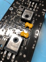
1) The mica caps - at least the CDE ones I'm using - have the leads flush with one side of the cap, not always the side with or without the text markings. I placed the flush side down to help keep things stable and low profile, especially on the rear mounted caps.
2) Be careful with the placement of the mod caps for Q13, Q14. These mosfets have C11 and C12 within their footprint on the top layer, so you'll have to mount the mod cap offset to clear those caps.
3) If you haven't finished the board yet and looking to do the mod, I would recommend mounting the mod caps before you put the higher profile parts in place - electrolytics, 5w resistors, etc - this will make poking around in there with a hot iron much easier.
I think I've finally gotten everything soldered for my build, can't wait to start wiring it up and try out the V4H!
Greg
FWIW, I just completed my V4H rev 1 mod using silver mica caps. Everything fits as expected, but I have just a few tips on using the larger mica caps.
1) The mica caps - at least the CDE ones I'm using - have the leads flush with one side of the cap, not always the side with or without the text markings. I placed the flush side down to help keep things stable and low profile, especially on the rear mounted caps.
2) Be careful with the placement of the mod caps for Q13, Q14. These mosfets have C11 and C12 within their footprint on the top layer, so you'll have to mount the mod cap offset to clear those caps.
3) If you haven't finished the board yet and looking to do the mod, I would recommend mounting the mod caps before you put the higher profile parts in place - electrolytics, 5w resistors, etc - this will make poking around in there with a hot iron much easier.
I think I've finally gotten everything soldered for my build, can't wait to start wiring it up and try out the V4H!
Greg
Attachments
I am still waiting for an answer, for EXICON mosfets, do I need the mods done?
Thank you.
I asked this and Shaan responded in PeeCeeBee V4H GB:
The Exicon MOSFETs are less in need for the mod than Renesas ones, but will have the same benefits which are stability and slew-rate increase.
I am using Exicons and have decided to do the mod.
Greg
Last edited:
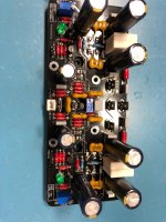
After updating to Rev1, my build is almost completed. It has been on for 5 days straight, even through the nights. I need to build an 12v trigger/softstart circuit asap!
The bass is incredible! 4 ohm load, ribbon speakers. After switching amps, my dog spent the day looking at the speakers. Guess also he noticed an improvement in the lower regions.
Next up is ground loop breaker and cleaning up wiring. Had an ebay upc1237 stereo protection board, but they dont work nicly with dual mono(gnd loop).
Hi Medisinmannen.
Great to know that!
Revision 1 has upgraded the amp to its full potential. Now you can listen to it for years to come and enjoy the true flavor of peeceebee. After the mod I have been listening to the amp everyday. And in fact the v4h is sounding better than v4 in my speakers. I guess users who heard both and reported the same were right after all. 🙂
After updating to Rev1, my build is almost completed. It has been on for 5 days straight, even through the nights. I need to build an 12v trigger/softstart circuit asap!
The bass is incredible! 4 ohm load, ribbon speakers. After switching amps, my dog spent the day looking at the speakers. Guess also he noticed an improvement in the lower regions.
Next up is ground loop breaker and cleaning up wiring. Had an ebay upc1237 stereo protection board, but they dont work nicly with dual mono(gnd loop).
Hi,
I use those for dual mono, boards are easily splittable (pre cutted), no connexion between them.
The description did not say that it's also temporised (about 2 sec).
Modules de protection stereo pour haut parleur 12V 16A (La paire) - Audiophonics
Hello Shaan,
In an earlier post, it was mentioned that R27-R30 should be 550R; however, in the most recent REV1 post, you mentioned replacing those resistors with 100R. I was wondering which resistors are the correct ones? Thank you!
Bao
In an earlier post, it was mentioned that R27-R30 should be 550R; however, in the most recent REV1 post, you mentioned replacing those resistors with 100R. I was wondering which resistors are the correct ones? Thank you!
Bao
Hello Shaan,
In an earlier post, it was mentioned that R27-R30 should be 550R; however, in the most recent REV1 post, you mentioned replacing those resistors with 100R. I was wondering which resistors are the correct ones? Thank you!
Bao
Hi Bao.
100R is the final value of the gate resistors. Should be used with the Rev1 mod.
- Home
- Group Buys
- PeeCeeBee V4H GB