Have you tried a bipolar CCS? In theory the bipolar is more linear and more predictable.However the fet defect might be nicer.
I think DN2540 is obsolete now. A depletion type if I am right? More like a jfet or vacuum tube. Again a bipolar CCS would be interesting and what best sets standing current. BC327-40 could work. An emitter resistor almost ensures linearity and is the current setting. Most MOS FET and all bipolar are enhancement (?) devices. The CCS for them look different. Bipolar types need about 0.55 to 0.7 volts to to switch on. This means a calculated design will be very close to actual result. Other devices may spread 2 to 4 volts.
Hi Everyone. Some help if you could. I have an application where Schotkey diodes would suit. I am using Soft Recovery diodes right now. The advantage a soft recovery gives is that when the diode reverse biases the switch off it is soft switching and is rather better than any attempt to do filtering of a standard diode. The noise of a standard diode is rather large. Enough to to swamp out AM radio. Soft diodes are high loss as a down side.Slightly worse than standard one I suspect ( 10 % ? ).
https://uk.farnell.com/vishay/sbyv2...y=https:en-GB/Element14_United_Kingdom/search
On trying Schotkey diodes before I was suprised how I didn't like what I heard. A rather cold closed in sound. This must be that I was doing somehing very wrong as on paper these didodes should be the best. Being fragile if abused and leakage are said to be trouble with them. The arguement in favour of them is it is not really a PN junction. Thus no residual charge to leap out of them when reversed biased.
This below would suit my application and JLH. I really need the 1/2V plus advantage of reduced loss this would bring.
https://cpc.farnell.com/on-semiconductor/mbr1045g/diode-schottky-10a-45v/dp/SC07390
I saw a MOSFET rectifier using PMOS and current mirror ( imbalanced type ) that claims to better all rectifiers. As a PMOS can be reversed this is part of how it works. It needs a very small error voltage to synthisise the PN junction. As it said the error is due to Ron only. Make Ron very small to make Vdg very small. We are talking far less than Vce of a tranistor which in itself can be very small . Seems to be too good to be true. When I useds an FET as a soft start with precautions it gave up after a month. Doubtless I missed something as a month is a very long time and was close to sucess. Two circuits did the same. Perhaps like CMOS switches I should have pulled it hard off below 0V. A MOSFET switch can have surprisingly low distortion. Less bad than a fuse I think.
Any thoughts?
On trying Schotkey diodes before I was suprised how I didn't like what I heard. A rather cold closed in sound. This must be that I was doing somehing very wrong as on paper these didodes should be the best.
Which schottky diode was that?
I bought a chinese JLH kit since it came with the PCB and the drilled aluminum angle pieces. I'll probably use most of the kit pieces except semiconductors, which I have on hand.
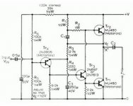
I got power transistor samples from on semi: MJ15003, MJ21194, MJ15022, MJ15024. I've got 5x of each, and each amplifier needs 4 transistors.
I gather that MJ15022 and MJ15024 are very similar transistors.
Which configuration would you choose for your build:
1. MJ15022 x4 Left, MJ15024 x4 Right
2. MJ15024 Q1 & Q1A, MJ15022 Q2 & Q2A
3. MJ15024 Q1 & Q2, MJ15022 Q1A & Q2A
Co-incidentally, I have just finished building a version of this with 4 output pairs (MJ15003) and running off +/- 38 volts. The driver (at the moment) is a sziklai pair and the amp delivers 75 watts into 8 Ohms and about 145 watts into 4 ohms before clipping, both with distortion below 0.05%. At a push, it will give 80 watts at 0.1 Now for some more listening test 😱
The flexibility of the JLH design still amazes me.
Mike
The flexibility of the JLH design still amazes me.
Mike
Sorry, to answer your question,
I would get hold of some more MJ15003s from a reputable source and use those.
Don't forget that you are going to have to cherry pick the devices by their Hfe value as the accepted reccomendation is to use those with the higher Hfe in the lowr transistor position.
Regards
Mike
I would get hold of some more MJ15003s from a reputable source and use those.
Don't forget that you are going to have to cherry pick the devices by their Hfe value as the accepted reccomendation is to use those with the higher Hfe in the lowr transistor position.
Regards
Mike
Which schottky diode was that?
Sorry I don't remember. My friend john says although not having minority carriers they do strange things which shows as RF noise. I have no idea if that's the reason.
Sorry I don't remember. My friend john says although not having minority carriers they do strange things which shows as RF noise. I have no idea if that's the reason.
With a diode that switches quickly it still has to deliver the same energy as one that switches relatively slowly to charge the power supply capacitor.
To do this the width of the pulse (analagous to time) will diminish but the peak height (voltage) will increase. The sharper the transient the more spurious the electrical effects will be.
You would do better to use a low resistance powdered iron core suppression choke between your bridge rectifier and the supply capacitor. The downside of this is the supply voltage will reduce a little - Silicon Chip magazine published an article giving the detail in connection with a 20 Watt Class A project which was sold in kit form.
The mains supply in Australia can vary ,higher in some areas, and some enthusiasts experienced problems with transformer buzz noises - ripple on the supply. The supply in this design used 30,000uF per supply rail.
I have a JLH 1996 which did not have this problem but I included the chokes anyway on the basis this would improve the supply and I am happy with the result.
Sorry I don't remember. My friend john says although not having minority carriers they do strange things which shows as RF noise. I have no idea if that's the reason.
Reason I asked is because not all Schottky are good enough. My best diode is not a Schottky but it is more Schottky in its parameters. The Schottky you linked above for example, is not good enough. It is more similar like the common MUR ultra-fast diodes.
I got lucky and could use soft recovery diode sbyv28 100 that is 3.5 amps and 100v. When reverse biased instead of going into abrupt switch off they go on a slope. Contrary to my assumption they are low capacitance. Logically right as high speed. I use two diodes and a centre winding to keep losses low. RS do good prices. I suspect this would suit JLH and could reduce high frequency tizz.I could imagine more important than fancy transistors.
After much thought I rejected even the Quasimodo as it's simplicity is still complex when I tried to replicate it. I gave up with oscilloscopes and use a simple am radio close by. One has to be careful with that as single 10nf capacitance across each diode will pass that test. Alas the energy is just spread almost into the audio band with audio band consequences. Soft diodes almost make the problem go away.
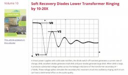
In an article in "The Audio Amateur" -first issue in 1994 Rick Miller measured RFI differences between rectifier diodes in simple capacitor-input power supplies.
The diodes tested were in best to worst order were GI851, BYV28-100, and 1N4002. The measured difference between the first and last was 10 dB over the test frequency range of 10kHz to 1.8MHz although in the cases of the GI851 the RFI frequency range is reduced to 500kHz and with BYV28-100 the reduced RFI range is to 900kHz.
The GI851 is a soft recovery diode with Trr of 200ns, the BYV28-100 being a high-speed type with Trr of 35ns.
At the time of publication of the article it was noted there had been advertisements for International Rectifier HEXFRED diodes with ultra-fast soft recovery Trr 18ms.
One of the benefits claimed for these was these do not exibit a tendency to "snap off" during recovery - producing a controlled non-ringing recovery wave-form, resulting in low RFI which behaved in the same manner as GI851.
The context of the main article which this piece accompanied was more DAC960 modifications by Gary Galo - Pooge 5.5. It was noted that modifications to a Hafler to include high-speed diodes in the bridge rectifier were more dramatic than results for DAC or pre-amplifier applications.
The range of diode product now available would have to provide a wider range of choice than in 1994.
This is a good debate as it is easy to try and costs very little. I have used 1N4148 when just an op amp. I doubt any snubber should be used with soft types.
This is a good debate as it is easy to try and costs very little.
More serious than that, people may tweak the speaker, the output stage, VAS, capacitor, etc. without realizing that the bottleneck is only with rectifiers (my experience). This may happen if we think that rectifiers cannot be a serious problem, which is wrong. Same like many years ago when many engineers think that great amps can be built from mediocre transistors.
I have used 1N4148 when just an op amp.
I have compared by ears power rectifiers in power supply but not yet with small signal diodes like 4148. I just decided to go straight with the best ones, and find out later on (which is quite complex to do) if they do sound different. Good ones are expensive I don't know why, probably just because its new old stocks.
Good ones are some of those with 1Sxxxx (or BATxx). The original Hitachi amp for example uses 1S2076. Many vintage amps used similar diodes. I think I'm using 1S1588 in my Hitachi amp. The germanium 1N270 looks good on paper but more 'expensive' that I didn't want to find out.
For small-signal rects you can use dirt-cheap stuff (like DIP or "button" bridges) and snub heavily right at the xfmr not across diodes in the bridge (can be reduced to two resistors and a single cap - low cost). Can also be "extended" to slightly more power circuits, like headphone amps etc.
Still working towards building the 1969 version to power 600 Ohm headphones and I have a couple of questions that hopefully someone can help me with.
Is it always better to use higher gain transistors for TR3 and TR4? I bought enough BD139-16 and BC559-C to match channels for hfe and ended up with a couple of pairs of each. These already have higher gain than the original transistors but wondering if I should use the pairs with the highest gain.
Is there any reason to choose a cap multiplier supply over a 3 pin regulator? I have some LM338K in the parts bin and it makes for an easy solution to regulation so I am leaning in that direction.
And the last is based on my very limited theoretical background… I noticed in simulations that the light loading on the outputs extended the HF knee by a considerable bit, it occurred to me that slower devices for the outputs might be usable or even desirable at those positions so I acquired some (what I hope are original) homotaxial RCA’s to try. Assuming I can get the hf extension I am looking for out of them, what is the best way to check the stability of the amplifier into the light load? I have an old 15Mhz scope and an AF generator, is there a way to excite and see HF oscillations with the equipment I have?
Thanks,
Marty
Attachments
- Home
- Amplifiers
- Solid State
- JLH 10 Watt class A amplifier