You are right that the stabilised current through In- is inversely proportional to R(z).
But why would or could a high value undermine the advantages of a CFA.
COD and constant BW are not affected, true ?
Hans
Strike the comment about undermining Hans. Many parameters would be worse under normal conditions by lowering Rz, as also including distortion. COD is something I have not looked at theoretically as of yet. This is why the translation has set the output buffer at Z(out) = 0 for this reason.
It has been thought for decades that COD is critically important, or equally lowering Z(out) toward zero. This is currently being experimented on using CFA's.
Simulations are not an effortless way to instant knowledge, they do not provide knowledge and do not predict anything.
Simulations are a vital tool for those with lesser knowledge to efficiently gain an understanding of how networks behave, particularly when variances can easily be made to observe changes that reinforce or deny what we believe. In that sense they are wonderful.
What is considered most interesting is in the finding of unexpected and unexplainable anomalies. A case in point is that of Paul finding early onset. This has led to seeming 100's of posts amongst the DIY community, including mine. I am not sure if anyone, including you, would disagree on this point.
Sorry Chris... I did it again. I can't get this out of my head.
Sorry Chris... I did it again. I can't get this out of my head.
No worries. You have no idea how many people do this. I once seriously thought of having my surname legally changed to that of my forebears - Pavel. Then I decided that even that might not solve the problem!
Yes definitely a numerical error but on your side 🙂For Rz=100Meg, ratio Ic/V(b,e) =38m* 200k/100,000k =8u (sim 71u significant error, possibly numerical?).
Cheers,
38m*200k/100Meg= 76u.
My sim gave 75.8u.
Hans
Hans,Yes definitely a numerical error but on your side 🙂
38m*200k/100Meg= 76u. My sim gave 75.8u. Hans
That's nice to know, that it was my numerical error and not LTspice resolution.🙂
Ian
To be even more precise, 38e-3/(1+(1K+100Meg)/200K)=75.8u, absoltely exactly the figure that LTSpice produces.Hans,
That's nice to know, that it was my numerical error and not LTspice resolution.🙂
Ian
Hans
I'm sorry but I can't agree with you on this because I can't see any current feedback in this circuit with no Rg -- the current through Rf is flowing the wrong way for feedback. We think of CFA feedback current from the output to the inverting input (with a positive input). But not so in this circuit.Surely we can agree that current is being fed from the output through the feedback network back through the transistor into the heart of the circuit. And if we wish to consider an Rg with the Rf, Hierfi pointed out that the circuit would operate virtually identically if the Rf / Rg feedback network drove a unity gain buffer which drove the inverting input through an Rg || Rf resistor..: Originally Posted by IanHegglun
My analysis assumes voltage control of the input transistor (Ic=gm*Vbe) and the current flowing through Rf is entirely the input transistor emitter current which flows from emitter to output. .....So I don't see any indication of "current feedback" using these equations, nor that the Early effect upsets voltage feedback as the controlling mechanism. Or have I looked at it the wrong way?...
With an Rg you can get the current direction to reverse through Rf. But how does this introduce current feedback to this circuit? Just because current is flowing through Rf from the output does not mean we have current feedback because current flows through a VFA's Rf feedback resistor too but we don't call that current feedback. We have to be consistent in both cases to be consistent🙂.
The DIT does not differentiate between CFA and VFA -- it is just your interpretation of the DIT values that gives you that viewpoint.Middlebrook's Double Injection Technique verifies that significant current feedback is occurring along with voltage feedback at the inverting input, sustaining this viewpoint.
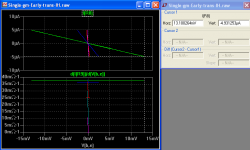
I found the current through the 'ro' is a local current loop from the gm source only with a constant peak current of 5uA for 1V input (ro=200k). It's current does not change with the loading on the mirror which changes the feedback loop gain. See attached plot (R8 is the Early ro resistor). So no indication that this restive part is affected by changing the feedback loop gain. An "imperfect" transconductor does not support the possibility of current feedback.This Early effect discussion was introduced simply to point out that the transistor is not acting as a perfect transconductor, and that there is a resistive, non-(voltage-controlling) transconductive path for current to flow from the inverting input to the low impedance current mirror input
The analysis I used with a pure transconductance with only voltage feedback gives the correct rations (thanks Hans) for Ic/Vbe in the presence of an ro restive component.when the feedback loop gain is varied by Rz ... and with no Rg for a unity voltage gain CFA..
I also conclude that only the old style voltage feedback taking place in this circuit. Therefore the CFA name is a misnomer for this circuit.
Cheers,
IH
Attachments
I'm sorry but I can't agree with you on this because I can't see any current feedback in this circuit with no Rg -- the current through Rf is flowing the wrong way for feedback. We think of CFA feedback current from the output to the inverting input (with a positive input). But not so in this circuit.
With an Rg you can get the current direction to reverse through Rf. But how does this introduce current feedback to this circuit? Just because current is flowing through Rf from the output does not mean we have current feedback because current flows through a VFA's Rf feedback resistor too but we don't call that current feedback. We have to be consistent in both cases to be consistent🙂.
The DIT does not differentiate between CFA and VFA -- it is just your interpretation of the DIT values that gives you that viewpoint.
I found the current through the 'ro' is a local current loop from the gm source only with a constant peak current of 5uA for 1V input (ro=200k). It's current does not change with the loading on the mirror which changes the feedback loop gain. See attached plot (R8 is the Early ro resistor). So no indication that this restive part is affected by changing the feedback loop gain. An "imperfect" transconductor does not support the possibility of current feedback.
The analysis I used with a pure transconductance with only voltage feedback gives the correct rations (thanks Hans) for Ic/Vbe in the presence of an ro restive component.when the feedback loop gain is varied by Rz ... and with no Rg for a unity voltage gain CFA..
I also conclude that only the old style voltage feedback taking place in this circuit. Therefore the CFA name is a misnomer for this circuit.
100% correct.
Ian,Hans,
That's nice to know, that it was my numerical error and not LTspice resolution.🙂
Ian
To my opininion there is still one thing in your very nice calculation that is incorrect, being the use of Ro.
The way you treat Ro is as if Va is 0 Volt.
But 200K with 24V supply means a Va of -176 Volt.
So when changing the voltage over Ro with +/- 1 Volt as in your Sim, current does not change +/-5uA but only by +/-0.6uA.
Hans
I don't know how to interpret this. Are you saying that a CFA employs both current and voltage feedback? If so, then we agree here. So what is the dispute about?
Not exactly, I still think CFA feedback is voltage, but if we agree on a definition and/or tests which decide there is a part of or it is current feedback, I will accept it.
Ian,
To my opininion there is still one thing in your very nice calculation that is incorrect, being the use of Ro.
The way you treat Ro is as if Va is 0 Volt.
But 200K with 24V supply means a Va of -176 Volt.
So when changing the voltage over Ro with +/- 1 Volt as in your Sim, current does not change +/-5uA but only by +/-0.6uA.
Hans
Hans,
Whatever Va value, a variation of +/- 1V applied on 200k gives a current variation of +/- 5µA.
That's an open door, but it does not apply to this situation.Hans,
Whatever Va value, a variation of +/- 1V applied on 200k gives a current variation of +/- 5µA.
But I made an error in my previous posting. Current does not change from +/- 5uA, to +/- 0.6uA, but to 0.6uA less being +/- 4.4uA.
Let me try to explain.
Ro=(-Va+Vce)/Ic.
Ic=1mA, Vce=24Volt and Ro is set at 200k.
Hence Va=-176 Volt.
When Vce becomes 25 Volt, Ro= (176+25)/1e-3= 201K.
Current through Ro becomes 25V/201K=124.4uA and not 125uA, so it is 0.6uA less as with a fixed 200K resistor.
Hans
But why would or could a high value undermine the advantages of a CFA.
COD and constant BW are not affected, true ?
Hans
In rethinking this, it is suspected that if you use small input voltage for Vin, as in the uV region, Middlebrook analysis would reveal the device as a VFA amplifier. This is for reasons that Z(In-) rises under small signal conditions in relation to the Thevenin feedback Z(Th). Hence the higher the value of Rz the stronger it becomes a VFA and the greater the amplitude of early onset to turn into a CFA.
The issue with reducing Rz is that the COD would decrease for reasons that the gain drops. Reducing gain is considered a critical disadvantage to sustaining high COD. Rz being in parallel with Cz is expected would increase BW as Rz drops.
I'm sorry but I can't agree with you on this because I can't see any current feedback in this circuit with no Rg -- the current through Rf is flowing the wrong way for feedback. We think of CFA feedback current from the output to the inverting input (with a positive input). But not so in this circuit.
So then you would argue that this is a current feedforward circuit? Really? Current moves between the output and input. It has to be fed somewhere.
With an Rg you can get the current direction to reverse through Rf. But how does this introduce current feedback to this circuit? Just because current is flowing through Rf from the output does not mean we have current feedback because current flows through a VFA's Rf feedback resistor too but we don't call that current feedback. We have to be consistent in both cases to be consistent🙂.
We are already wholly consistent. No input stage collector current is exchanged with the feedback network in a VFA. But collector signal current flows through the feedback network in a CFA.
The DIT does not differentiate between CFA and VFA -- it is just your interpretation of the DIT values that gives you that viewpoint.
You are not the first to make the mistake of asserting that I claim that DIT differentiates between CFAs and VFAs. I don't know why people keep doing this. I have never claimed that DIT is topologically sensitive and I never will. (Hans however, proposes a test for topology.) DIT measures current and voltage loop gains at a given point in a circuit and associates them with the total loop gain. The type of loop with the lesser gain has the greater amount of feedback. I suggest you try Middlebrook at the inverting input of one of the CFA's you've been working with to see this. You'll see that the voltage loop gain exceeds the current loop gain and that therefore, the amount of current feedback exceeds that of voltage feedback. Move the test to the output and the reverse will be true. Or try it at the inverting input of a typical VFA design.
I found the current through the 'ro' is a local current loop from the gm source only with a constant peak current of 5uA for 1V input (ro=200k). It's current does not change with the loading on the mirror which changes the feedback loop gain. So no indication that this restive part is affected by changing the feedback loop gain.
Of course not! Why would it be? Ve changes minimally with loop gain. I made this point when I first brought the matter up. But vbe and therefore gm vbe changes at sufficiently high loop gains in a way that is affected by the current flowing through ro.
An "imperfect" transconductor does not support the possibility of current feedback.
DIT disputes your conclusion.
The analysis I used with a pure transconductance with only voltage feedback gives the correct rations (thanks Hans) for Ic/Vbe in the presence of an ro restive component.when the feedback loop gain is varied by Rz ... and with no Rg for a unity voltage gain CFA.
If we remove the phrase "with only voltage feedback" from the above, and I assume that the phrase "pure transconductance" applies only to the gm vbe portion of your model, then I can accept the statement.
I also conclude that only the old style voltage feedback taking place in this circuit. Therefore the CFA name is a misnomer for this circuit.
Forgive me for injecting a bit of levity here, but the following from that great philosopher Tom Petty comes to mind:
Listen, it don't really matter to me, baby
You believe what you want to believe
You believe what you want to believe
This is probably true of all of us to some extent.
Does it cause you to wonder that Analog Devices, Linear Technology (before ADI bought them) and Texas Instruments, to name a few major semiconductor manufacturers, all explain the operation of their CFAs by using the term "current feedback"?
Imagine the competitive advantage for one of the manufacturers if they were to say, "The other guys are explaining it all wrong - they don't even understand how the thing works. Here's how it really works:"
And yet this doesn't happen. Why?
Or that the patent grant in the '80's for one of the first ICs to be called a CFA explains it with current feedback? IIRC, the patent was titled "Current Mode Amplifier." However, the explanation of the device's operation was rife with the term "current feedback."
In addition, Dick Marsh makes it clear that the IEEE calls the CFA a Current Mode Amplifier. My understanding is that this is because the term "current feedback" historically was applied to any amplifier, even one with a VFA gain block, which sensed the current through a load by looking at a voltage drop across a small, usually ground-referenced, sense resistor. Now there is a misnomer if ever there were one!
In addition, Dick Marsh makes it clear that the IEEE calls the CFA a Current Mode Amplifier. My understanding is that this is because the term "current feedback" historically was applied to any amplifier, even one with a VFA gain block, which sensed the current through a load by looking at a voltage drop across a small, usually ground-referenced, sense resistor. Now there is a misnomer if ever there were one!
From a Thevenin perspective it appears performing as a current limiting feedback amplifier, supporting that Current Mode Amplifier is a more accurate and less confusing reflection of a CFA
From a Thevenin perspective it appears performing as a current limiting feedback amplifier, supporting that Current Mode Amplifier is a more accurate and less confusing reflection of a CFA
Far be it from me to question assigned names, but I don't find "Current Mode Amplifier" to be particularly informative. I have to look up what is meant by that. And I don't find a clear answer:
Consider the contents of the Abstract from this paper: Current-mode amplifiers - IEEE Conference Publication
Or the ever-available Wikipedia written by ???
Current-feedback operational amplifier - Wikipedia
Can you point us to an authoritative definition of "Current Mode Amplifier"?
Far be it from me to question assigned names, but I don't find "Current Mode Amplifier" to be particularly informative. I have to look up what is meant by that. And I don't find a clear answer:
Can you point us to an authoritative definition of "Current Mode Amplifier"?
Ah... do you mean by authoritative as pointing to someone other than just me? Ok... in that case no. It seems I must now resort to argument as opposed to "appealing to authority"... dammit (oops... excuse my language).
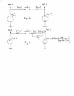
Thevenin's theorem translates a network into a voltage source connected to an open circuit resistor.
Thevenin's theorem - Wikipedia
Figure 2 shows the resistance elements attached to the two V Thevenin sources prior to connection. The value of V Thevenin 2 is shown as a function of Vout, that in a previous post was shown being included in a visual Thevenin translation that could replace the Rf, Rg feedback network.
From the perspective of Figure 2 there is no relationship of the value of VTh2 to RTh2 other than a greater or lesser drop between VTh1 and VTh2. This is to state that the division ratio of RTh1 and RTh2 remains constant independent of gain, hence feedback isn't relevant in the determination if a CFA is a v.f. or c.f. amplifier. It is thought that the relationship of RTh1 to RTh2 are the only terms relevant, being measurable independent of feedback.
With gain, all that changes is the magnitude of the voltage drop across VTh1 and VTh2. Hence the term "feedback" isn't relevant if it is irrelevant of gain. This is under circumstances identifying a device c.f. or v.f. device. This leaves us with "CA" as even more confusing if we drop F in the mnemonic. By the way, current limiting feedback doesn't work either by such reasoning. For want of a better term it seems that CMA isn't all that bad.
Attachments
- Home
- Amplifiers
- Solid State
- Current Feedback Amplifiers, not only a semantic problem?