Under steady state conditions the Thevenin buffer disappears, being undetectable by the In- terminal, hence the value of Vbe diminishes to a value causing 2 uAmp’s to flow through 500K Ohm.
Let me correct myself on this. The Vbe drops by an amount in relation to existing DC bias current passing through an NPN/PNP pair on the input network.
Hi All,Perhaps Ian will weigh in on the extent to which there is or is not a significant problem with LTSpice transistor models. Or maybe someone else.
Sorry, I was away for a while. From your latest sims the LTspice Early model seems to be fine -- a question mark is now on the VBIC for Early effect. When I first raised the issue I did not understand why the Ic6/Vbe ratio changed with the Rz loading resistor. I think I can now explain what is going on after doing some analysis. I don't have the time now to post the analysis.
Briefly, I found Vout bootstraps the emitter and when the loop gain is large enough, Rz ~ Ro and then the input transistor does not need to feed as much current to the mirror to get the required output voltage. So where does the unwanted collector current go? It goes into ro internally inside the model. That's what I didn't see before.
The internal gm is not changing, it cannot change by external feedback!, but the Ic/Vbe is changing as evidenced by simulations; the difference must flow into ro internally.
I checked this with Herve's single ended simulation by disabling the Early voltage (you can also specify VAF=0 for no early), then put a 1Meg for ro across the transistor. Reading the AC current through ro it is the same as IC when Rz is 10G. So all the Ic (now only from gm) current now flows through the Early ro (IR8) with 10G loading (red and green are on top of each other). File attached. Please let me know if I have it all wrong.
I include a .trans file showing the slopes Ic vs Vbe do change with Rz loading as per AC sims. A useful reality check.
BTW I also show how to use .Step between model variants (it also works for different types like GP and VBIC).
Cheers,
.
Attachments
I think I found a much easier way to prove that the Early effect is mainly responsible for the change in ic/vbe.
When Vce wouldn't change , we don't have any interfering early effect changing the current flow.
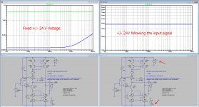
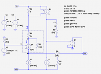
So by changing the supply voltage in the same way as the input voltage moves, Vce remains constant at 22.78 Volt.
By doing this, nothing has to be changed to the transistor model, a big advantage to my opinion.
See image below for the results. Fixed voltage at the left.
In both cases exactly the same transistor models have been used.
Hans
When Vce wouldn't change , we don't have any interfering early effect changing the current flow.
So by changing the supply voltage in the same way as the input voltage moves, Vce remains constant at 22.78 Volt.
By doing this, nothing has to be changed to the transistor model, a big advantage to my opinion.
See image below for the results. Fixed voltage at the left.
In both cases exactly the same transistor models have been used.
Hans
Attachments
I think I found a much easier way to prove that the Early effect is mainly responsible for the change in ic/vbe.
When Vce wouldn't change , we don't have any interfering early effect changing the current flow.
So by changing the supply voltage in the same way as the input voltage moves, Vce remains constant at 22.78 Volt.
By doing this, nothing has to be changed to the transistor model, a big advantage to my opinion.
See image below for the results. Fixed voltage at the left.
In both cases exactly the same transistor models have been used.
Hans
Excellent thinking Hans... removing a variable from consideration.
So by changing the supply voltage in the same way as the input voltage moves, Vce remains constant at 22.78 Volt.
By doing this, nothing has to be changed to the transistor model, a big advantage to my opinion.
See image below for the results. Fixed voltage at the left.
In both cases exactly the same transistor models have been used.
Hans
Cascode
🙄
Hi All,
Sorry, I was away for a while...
...BTW I also show how to use .Step between model variants (it also works for different types like GP and VBIC).
Cheers,
Thanks for checking back in, Ian. Our understandings of circuit operation are the same.
For me, the remaining mystery is that although I found a value of negative ro in Post 2210 that reduced the variation of ic/vbe with loop gain from 300:1 to 3:1, I could not get to 1:1. So is there some other non-Early Effect going on here? It would have to be frequency-independent as the post shows.
I think I found a much easier way to prove that the Early effect is mainly responsible for the change in ic/vbe.
Hans
Yes, nice and simple.
Early onset (and late offset) effects are understandable from a Thevenin perspective...
Hierfi, I'm puzzled by what you mean by "Early onset (and late offset)".
Yes, if it were something that needed fixing, that would be an obvious solution. But there's no indication that it needs fixing.
Being part of the input capacitance, a change in the collector-base junction capacitance, which is a necessary condition of signal transmission, is also a change in bandwidth, transconductance and all other parameters. The Miller effect has been publicly known for one hundred years (obviously not to everyone) so you do not need to prove it (cannot be done mathematically anyway).
Hierfi, I'm puzzled by what you mean by "Early onset (and late offset)".
Hi Chris,
I was addressing the cause for early onset and late offset to occur, not the cause for the nature of the waveform. Hence, I used the term incorrectly. Determining the cause is essential in determining the potential impact this has and how this can be addressed.
Prior to early onset, as ending in late offset, the network stabilizes equal to the open loop transconductance current as calculated. For small input signals Vin-, the current can be dominantly responding in relation to Rz. The issue here is that the amount of corrective feedback current is a function of Vin / Rin, whereupon this current is inversely proportional to Rz. This is to suggest that high values of Rz can critically undermine the advantages of using a CFA as removing current drive. Upon this finding I have already connected 100K Ohm resistors from the Tz node to ground on a couple of AD844's in my system.
You are right that the stabilised current through In- is inversely proportional to R(z).high values of Rz can critically undermine the advantages of using a CFA as removing current drive. Upon this finding I have already connected 100K Ohm resistors from the Tz node to ground on a couple of AD844's in my system.
But why would or could a high value undermine the advantages of a CFA.
COD and constant BW are not affected, true ?
Hans
"Other camp" is not a problem.
It's just that you said, more than one time, that we -other camp- only think about a pure voltage feedback.
It is not true. I said the contrary in post #963.
Herve, I don't think I ever saw a reply to the response I wrote to the above:
Here is your statement from 963:
By the way, does forr agree? (Not your responsibility to speak for forr, I know.)
I don't know how to interpret this. Are you saying that a CFA employs both current and voltage feedback? If so, then we agree here. So what is the dispute about?No, because if you change Rg, you change the open loop gain, so the OLG will change.
Why not thinking there is space between pure current feedback and pure voltage feedback ?
By the way, does forr agree? (Not your responsibility to speak for forr, I know.)
I have never seen such a dense concentration of erroneous, confused and worthless assertions in one and the same thread. Why not make at least a tentative attempt to aquire a basic knowledge in physics, transistor properties and operation? Sound knowledge aquired the hard way in order to reduce dependence on all that fraudulent software-generated generic statistical trash. Simulations are not an effortless way to instant knowledge, they do not provide knowledge and do not predict anything.
I have never seen such a dense concentration of erroneous, confused and worthless assertions in one and the same thread. Why not make at least a tentative attempt to aquire a basic knowledge in physics, transistor properties and operation? Sound knowledge aquired the hard way in order to reduce dependence on all that fraudulent software-generated generic statistical trash. Simulations are not an effortless way to instant knowledge, they do not provide knowledge and do not predict anything.
🙂 😎
-RNM
Oops
Oops. I now know the GP model is working properly. My thinking was the ratio of Ic/Vbe should not change but I now know it does change in simulations and now from analysis (below). My apologies for this mea culpa😱. Differences with the VBIC model led me to a wrong conclusion. I won't use the VBIC here again, it's differences should be discussed in another thread.
------
Early effect analysis for Ic/Vbe ratio in a single ended CFA as a CFP
Reference circuit attached. Assumes AC analysts at Ic bias of 1mA, gm=38mA/V, Ro=ro=200k, Rz is the mirror loading as a variable.
Ico=gm*V(b,e) ;gm transconductance is from the Shockley equation (gm=Ic/Vt)
Ic=Ico+V(c,e)/Ro ;Ic is the terminal collector current, Ro is the Early collector conductance for GP (ro=VA/Ic)
Ic=gm*V(b,e)+V(c,e)/Ro . . . .eq(1)
Ve=Ie*Rf+Vout
Vout=Ic*Rz
Ve=Ie*Rf +Ic*Rz
Since Ie=Ic*(Beta+1)/Beta) (same as Ic/alpha)
Ve=Ic*(Rf'+Rz) . . . . .eq(2) where Rf'=Rf*(Beta+1)/Beta)
Use (1) and leave V(b,e) since we are after Ic/V(b,e)
Ic=gm*V(b,e) -Ve/Ro
use (2) Ic=gm*V(b,e) -Ic*(Rf'+Rz)/Ro
With closed loop RHS forces LHS to match, collect Ic terms to LHS
Ic(1+(Rf'+Rz)/Ro) = gm*V(b,e)
Ic = gm*V(b,e) / (1+(Rf'+Rz)/Ro)
Finally
Ic/V(b,e) = gm/(1+(Rf'+Rz)/Ro)
This tells us that feedback via Rf from the output causes the ratio Ic/Vbe in the input transistor to decrease, starting from gm when Rz becomes significant compared to Ro from the Early effect. When (Rf'+Rz)=Ro then the ratio Ic/V(b,e) is halved
for Ro=200k and Rf=1k, 50% ratio is when Rz =200k - Simulation gives 19mA/V with Rz=200k and Ro=200k (agrees).
For Rz=1Meg, ratio Ic/V(b,e) =38m* 200k/1000k = 7.6m (sim 6m almost same)
For Rz=100Meg, ratio Ic/V(b,e) =38m* 200k/100,000k =8u (sim 71u significant error, possibly numerical?).
My analysis assumes voltage control of the input transistor (Ic=gm*Vbe) and the current flowing through Rf is entirely the input transistor emitter current which flows from emitter to output. This analysis.agrees with simulations (eg attached). So I don't see any indication of "current feedback" using these equations, nor that the Early effect upsets voltage feedback as the controlling mechanism. Or have I looked at it the wrong way?
BTW my attached sim has a switch (.param sw=1) that allows the dc currents and voltages to be turned off (.param sw=0) so you can do a .trans simulation for AC readings. This is only possible when a transconductance source replaces Q6 with a resistor Ro=ro (and ideal sources for the others as well). It is a useful reality check for AC plots and for the small-signal equations which don't have supply voltages or bias currents. Plot d(Ic6)/d(Vce) to get the same as Ic/Vce in in AC run).
Cheers,
Hi Chris, All,The anomaly I found in the GP model was specifically the ratio of Ic6/Vbe. When the Tz termination resistance was varied in your test circuit (Post 1872 AD844) Current Feedback Amplifiers, not only a semantic problem? you found a massive unexpected drop from 38mS to 0.15mS!! when this should not change much at all because you are only altering the termination resistance of the output of the current mirrors and no change in the DC bias.
Oops. I now know the GP model is working properly. My thinking was the ratio of Ic/Vbe should not change but I now know it does change in simulations and now from analysis (below). My apologies for this mea culpa😱. Differences with the VBIC model led me to a wrong conclusion. I won't use the VBIC here again, it's differences should be discussed in another thread.
------
Early effect analysis for Ic/Vbe ratio in a single ended CFA as a CFP
Reference circuit attached. Assumes AC analysts at Ic bias of 1mA, gm=38mA/V, Ro=ro=200k, Rz is the mirror loading as a variable.
Ico=gm*V(b,e) ;gm transconductance is from the Shockley equation (gm=Ic/Vt)
Ic=Ico+V(c,e)/Ro ;Ic is the terminal collector current, Ro is the Early collector conductance for GP (ro=VA/Ic)
Ic=gm*V(b,e)+V(c,e)/Ro . . . .eq(1)
Ve=Ie*Rf+Vout
Vout=Ic*Rz
Ve=Ie*Rf +Ic*Rz
Since Ie=Ic*(Beta+1)/Beta) (same as Ic/alpha)
Ve=Ic*(Rf'+Rz) . . . . .eq(2) where Rf'=Rf*(Beta+1)/Beta)
Use (1) and leave V(b,e) since we are after Ic/V(b,e)
Ic=gm*V(b,e) -Ve/Ro
use (2) Ic=gm*V(b,e) -Ic*(Rf'+Rz)/Ro
With closed loop RHS forces LHS to match, collect Ic terms to LHS
Ic(1+(Rf'+Rz)/Ro) = gm*V(b,e)
Ic = gm*V(b,e) / (1+(Rf'+Rz)/Ro)
Finally
Ic/V(b,e) = gm/(1+(Rf'+Rz)/Ro)
This tells us that feedback via Rf from the output causes the ratio Ic/Vbe in the input transistor to decrease, starting from gm when Rz becomes significant compared to Ro from the Early effect. When (Rf'+Rz)=Ro then the ratio Ic/V(b,e) is halved
for Ro=200k and Rf=1k, 50% ratio is when Rz =200k - Simulation gives 19mA/V with Rz=200k and Ro=200k (agrees).
For Rz=1Meg, ratio Ic/V(b,e) =38m* 200k/1000k = 7.6m (sim 6m almost same)
For Rz=100Meg, ratio Ic/V(b,e) =38m* 200k/100,000k =8u (sim 71u significant error, possibly numerical?).
My analysis assumes voltage control of the input transistor (Ic=gm*Vbe) and the current flowing through Rf is entirely the input transistor emitter current which flows from emitter to output. This analysis.agrees with simulations (eg attached). So I don't see any indication of "current feedback" using these equations, nor that the Early effect upsets voltage feedback as the controlling mechanism. Or have I looked at it the wrong way?
BTW my attached sim has a switch (.param sw=1) that allows the dc currents and voltages to be turned off (.param sw=0) so you can do a .trans simulation for AC readings. This is only possible when a transconductance source replaces Q6 with a resistor Ro=ro (and ideal sources for the others as well). It is a useful reality check for AC plots and for the small-signal equations which don't have supply voltages or bias currents. Plot d(Ic6)/d(Vce) to get the same as Ic/Vce in in AC run).
Cheers,
Attachments
This forum is not meant to be used exclusively for Nobel prize winners in physics, nor is it very constructive to call people stupid.I have never seen such a dense concentration of erroneous, confused and worthless assertions in one and the same thread. Why not make at least a tentative attempt to aquire a basic knowledge in physics, transistor properties and operation? Sound knowledge aquired the hard way in order to reduce dependence on all that fraudulent software-generated generic statistical trash. Simulations are not an effortless way to instant knowledge, they do not provide knowledge and do not predict anything.
It is to help people, mostly DIY, in finding answers for their problems.
Calling Simulations tools that do not predict anything does not help anybody at all.
One should either offer some help by showing whatever road may or may not lead to a possible solution or do a step aside.
It's all up to you. 😀
Hans
I would be interested to know the reasons of your thinking.I have never seen such a dense concentration of erroneous, confused and worthless assertions in one and the same thread. Why not make at least a tentative attempt to aquire a basic knowledge in physics, transistor properties and operation?.
Hi Chris, All,
Oops. I now know the GP model is working properly...
Hi Ian, thanks for getting back to us on this. Your algebraic analysis looks good to me.
....For Rz=100Meg, ratio Ic/V(b,e) =38m* 200k/100,000k =8u (sim 71u significant error, possibly numerical?).
Numerical errors could explain why, while sim'ing with a transistor, I could not find a compensatory value of -Ro that would remove all variations in Ic/Vbe with Rz.
....So I don't see any indication of "current feedback" using these equations, nor that the Early effect upsets voltage feedback as the controlling mechanism. Or have I looked at it the wrong way?...
Surely we can agree that current is being fed from the output through the feedback network back through the transistor into the heart of the circuit. And if we wish to consider an Rg with the Rf, Hierfi pointed out that the circuit would operate virtually identically if the Rf / Rg feedback network drove a unity gain buffer which drove the inverting input through an Rg || Rf resistor.
Middlebrook's Double Injection Technique verifies that significant current feedback is occurring along with voltage feedback at the inverting input, sustaining this viewpoint.
Finally, it's worth noting that the importance of voltage feedback doesn't negate the existence of significant, even predominant (re: Middlebrook), current feedback.
This Early effect discussion was introduced simply to point out that the transistor is not acting as a perfect transconductor, and that there is a resistive, non-(voltage-controlling) transconductive path for current to flow from the inverting input to the low impedance current mirror input.
- Home
- Amplifiers
- Solid State
- Current Feedback Amplifiers, not only a semantic problem?