C4a and C4b form quite a resonant notch filter at the input and/or an antenna somewhere around 4MHz. I avoid doing this with bypass capacitors because the resonant spike can cause oscillation. If the input is grounded or has a low source impedance it could mess with the loop gain as well. It could be a non-issue but I avoid doing this on principle. If you don't want to remove one of the capacitors you can add some series resistance to one of them. 1 ohm would be enough.
For input signals it behaves like a notch filter but for RF it is a resonant antenna.
I have "tons" of RF/EMI in grid and in the atmosphere too. To avoid the second problem the best is a case of cheap but very effective 1mm galvanized steel or aluminum with AT LEAST 4mm thick in ALL walls.
If you have a furniture with the electronics, a very good idea is to paste (silicone or equivalent) a 1mm sheet of galvanized steel under the wooden shelves.
Preamp, DAC and headpnohes amps, working with small signals, are more sensitive. Class D amps too. A lot of DACs, headphones amps, class D amps have a case with thin aluminum walls. Like my old ODAC, tweaked and modded by me (in and out). With better case -thick aluminum walls- the sound is better in my house.
Off course, I refer to play good/very good recordings, with high/very high DR (dynamic range), in a clean system, without noise and distortion.
Last edited:
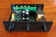
Finally assembled my AKSA Lender preamp after the chassis parts came back from the engineering shop. Had some cooling slots laser cut in the lid and all chassis parts eCoated. The latter is not as durable or aesthetically pleasing as anodizing, but it's a lot cheaper. Also swapped the Taiwanese carbon pots out for Bourns Cermet pots.
I'm relieved that the cooling slots made all the difference that I hoped for. Even without any openings in the bottom panel, the chassis is now cool - maybe 5 deg Celsius above ambient. It was like 50 deg C before the slots.
I decided to modify the input selector board (acquired a spare from a friend) and used the unused set of contacts to switch LED's on the front panel to indicate the input selected.
PS. The chassis before eCoating can be seen in post #863
Attachments

Last edited:
Good implementation. I prefer 1mm steel black paint coated too. Cheaper and better RF/EMI attenuation. And the small EI transformer seems far enough away.
By the way, can you tell us more about Bourns Cermet pots?
By the way, can you tell us more about Bourns Cermet pots?
Last edited:
Beautiful work, Skylar!
Can you explain what you did to the rear panel to get the LED outputs? You are using unused positions as LED contacts?
Can you explain what you did to the rear panel to get the LED outputs? You are using unused positions as LED contacts?
Good implementation. I prefer 1mm steel black paint coated too. Cheaper and better RF/EMI attenuation. And the small EI transformer seems far enough away.
By the way, can you tell us more about Bourns Cermet pots?
The chassis I used is made from 2mm alu, so not as good as steel in the RF department. But I had the bottom half of the chassis already - and it had the ideal footprint for this preamp. There is no audible hum pickup from the transformer, but I haven't measured it.
It was Hugh's FAQ's that originally put me onto the Cermet pots (search the page for "cermet"). I meant to use this model pot from RS, but it was out of stock and then I got a slightly different version - with plastic shaft, but still Bourns.
Beautiful work, Skylar!
Can you explain what you did to the rear panel to get the LED outputs? You are using unused positions as LED contacts?
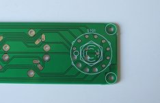
Yes, I implemented the unused pole of the Lorlin switch for the LED's. There are 3 poles and only two are used for the two channels. I drilled out the pin holes in the PCB and soldered wires to it before soldering the switch onto the PCB.
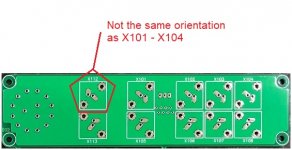
In the pic below, one can clearly see that the drilled holes don't have any traces going to them.
Maybe a new revision of the switch selector board can take those pins to a connector, in case others want to add LED's too?
Last edited:
Request:
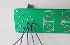
If there is ever going to be a revision of the boards, can X112 please be rotated 180 degrees?
It took me a day to figure out why one channel was low volume and playing on both speakers. I had soldered the wires leading to the RCA sockets the same as for the other sockets, not realizing X112 is different.
Attachments
That’s a great idea. I am sure JPS64 will do that if we ever make another run of boards.
Regarding X112, that’s news to me as I never used this selector board. I think JPS64 used one on his but did not mention it. So the polarity of the pins were switched?
Regarding X112, that’s news to me as I never used this selector board. I think JPS64 used one on his but did not mention it. So the polarity of the pins were switched?
Last edited:
Regarding X112, that’s news to me as I never used this selector board. I think JPS64 used one on his but did not mention it. So the polarity of the pins were switched?
Yep. Positive out went to ground on my left channel. Took me hours to find the problem. It's of no consequence if one uses the 12HP059 RCA sockets in the BOM which directly mount onto the selector board. Since I could not source those RCA sockets, I used short wire leads between the board and panel mount sockets. Of course, positive went to ground because I didn't realize the orientation was different on the one output socket.
I'm not saying there is a mistake on the selector board. It's just a pitfall for the unwary builder who uses panel mount RCA sockets.
Last edited:
Months ago I asked for the cermet in this thread but there was only silence.
In his last amps Hugh Dean does not use them. At least in the Naksa 80.
Hugh Dean's NAKSA 80 | Darko.Audio

Stepped! But the amp is 80 watts at 8 Ohms. How much steps? Hugh, are you here? Btw, cheap steel coated case 🙂
NVA designer/builder, over ninety years old and still active, is a fan of cermet.
NVA Design Criteria
In his last amps Hugh Dean does not use them. At least in the Naksa 80.
Hugh Dean's NAKSA 80 | Darko.Audio
Stepped! But the amp is 80 watts at 8 Ohms. How much steps? Hugh, are you here? Btw, cheap steel coated case 🙂
NVA designer/builder, over ninety years old and still active, is a fan of cermet.
NVA Design Criteria
* The input selector switch, where fitted, is wired to the input RCA jacks with teflon-coated, plated copper wire, as is the connection from selector switch to the volume control and thence to the input on the circuit boards. A small compromise.
* The volume control is of pure cermet type for minimal aural impact, even if it may feel coarse to the touch. The pot's tracks are linear to achieve close channel tracking, with a resistor added to simulate a log law.
Last edited:
There are two schools of thought on chassis materials.
Some designers prefer the non "magnetic" metal for chassis.
As an example the two amps above, that you refer to, use aluminium.
Some designers prefer the non "magnetic" metal for chassis.
As an example the two amps above, that you refer to, use aluminium.
In my experience a stepped attenuator is better than any Pot, from the comparisons that I have done.
Also the tracking between channels is far more accurate.
I have not compared a Light spead attenuator.
Also the tracking between channels is far more accurate.
I have not compared a Light spead attenuator.
Aluminum or cupper (expensive) are better, off course. But you need 4mm or more (Alu) in the walls.
And if it s a Phono, DAC or a Preamp, you have to be more careful about it being the signals of low magnitude.
The electrical grid and the atmosphere is increasingly polluted and that must be taken into account more and more. Fifty years ago there were hardly any junk that dirtied the spectrum as much as they do today.
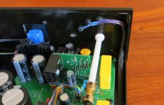
I think it is a steel case, black coated. And the PCB is over a aluminum sheet. In any case, that area has a good thickness!
But in an amp the signals are much higher magnitude.
My ODAC and my iFi iCAN (class A headphone amp) sound better with thick walls without any doubt!
I made a very a easy test. I put the iCAN under the 3 mm steel and the sound improved immediately.
Old picture:
By the way, my tweaked/modded/recabled headphones sound much better now with the tweaked/modded class AB Marantz! (after equalizing the bass boost due to the impedance mismatch: 120 Ohms vs 330 Ohms). And that the specifications of the iCAN are much better and it is class A.
But in an amp the signals are much higher magnitude.
My ODAC and my iFi iCAN (class A headphone amp) sound better with thick walls without any doubt!
I made a very a easy test. I put the iCAN under the 3 mm steel and the sound improved immediately.
Old picture:
An externally hosted image should be here but it was not working when we last tested it.
By the way, my tweaked/modded/recabled headphones sound much better now with the tweaked/modded class AB Marantz! (after equalizing the bass boost due to the impedance mismatch: 120 Ohms vs 330 Ohms). And that the specifications of the iCAN are much better and it is class A.
Last edited:
iFi Micro iCAN
Takstar ts-671 EQ: http://maty.galeon.com/WP-imagenes/soft/iZotope-RX-7-De-Hum-220-takstar-ts671-JRMC.png
Better with HPF at 210 Hz, Q=0.7
Marantz SR4500 A/V Receiver HT Labs Measures | Sound & VisionGanancia: 0dB, 10dB and 20dB user-selectable
Ratio señal-ruido: >117dB(A)
Total Harmonic Distortion(THD): <0.003%(400mV/150R)
Respuesta de frecuencia: 0.5Hz a 500KHz(-3dB)
...
Takstar ts-671 EQ: http://maty.galeon.com/WP-imagenes/soft/iZotope-RX-7-De-Hum-220-takstar-ts671-JRMC.png
Better with HPF at 210 Hz, Q=0.7
Last edited:
Hi Maty,
I understand what you are saying and I’m glad that you got good results with the steel plate.
However, as I stated in my previous post, some amp designers will not use any material that is attracted to magnets, including the screws. My Marantz CD player has an aluminium chassis with a “coating” of copper on the inside.
Both links that you posted clearly (if correct) say that aluminium chassis’ are used.
Is it black magic – I don’t know? I don’t have testing equipment to measure distortion or noise.
Attached, is my chassis solution for the Slewmaster amp using copper sheet and thick aluminium.However it’s taking forever to complete.
Looking forward to more of your record reviews in 2019.
Attachments
We have the induced currents in the magnetic walls and the RF/EMI from inside and outside. Many years ago only we have the currents and some RF/EMI inside.
Transformer, better outside or with a wall or blinded... as all we know.
The coating must be cleaned around the fixing screw (ground). Until Shiit made that mistake in at least one of his headphone amps, and secure some chinese hard.
Marantz CD, aluminum chassis. How much thickness? That is the question. A lot of small aluminum cases are only 1 or 2 mm. Like my original ODAC (now the case is inside other case, and tweaks inside) case and the iCAN. And without coating.
An example, the Tisbury passive preamp with the cheap and very good chinese DACT 21 steps. And wood front, within aluminum behind.
[Big IMG, link] http://wallofsound.ca/wp-content/uploads/2015/11/tis1.png
Btwh, how nuch money the copper?
******* *******
As RF/EMI in my house, I have "tons" of good/very good recordings, more of them are the best recording or pressing. With high/very high DR too, at least DR > 11 dB.
Off topic
It is incredible how much the sound can be improved with tweaks in the OS (Win 10 Pro 1709 64 bits). Now I am trying to emulate the sound produced by a predominant H2 profile, selectable -by user- depending on the music played, and without distorsion added. Hence, investigate the existing, wich add distorsion.
Last edited:
It is incredible how much the sound can be improved with tweaks in the OS (Win 10 Pro 1709 64 bits).
I would be interested to know more about that. I have Win10 version 1803 64-bit.
It’s still research stage , but spacecraft electronics enclosures that use carbon fiber composites doped with bromine make excellent RFI/EMI, gamma and heavy ion shields at 1/6th thickness of aluminum and a fraction of the mass. Basically, a lightweight super shield. The carbon fiber conducts along wall length as the Faraday cage. It does not get induced eddy currents. It has built in resistive damping. The heavy atoms like Br provide a heavy and wide nucleus cross section to absorb the higher energy radiation and high energy particles. For non hard radiation applications, the heavy halogens are not needed but the graphite layup must be done in a way that permits electrical conductivity.
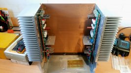
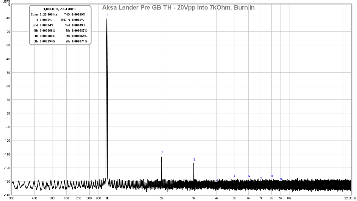
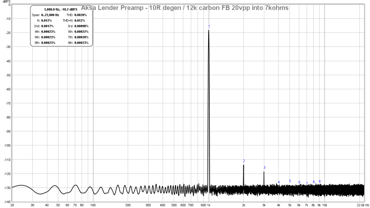
So maybe try carbon fiber enclosures for ultimate low noise case. For me, keeping the Preamp away from mains power cords and power transformers is most effective. I don’t even need a shielded case as FFT measurements show noise floor is battery like flat down to circa -120dB to -130dB. Here is Aksa Lender in open air sitting on wooden board.
Ally hats needed to measure is a sound card interface on your PC and REW software.
Last edited:
- Home
- Source & Line
- Analog Line Level
- AKSA's Lender Preamp with 40Vpp Output