That could very well be, I was only familiar with things from a long time ago. As you can imagine the merger got lots of bodies flying. 😉
Been there. Done it. Had it done to me 😉
Why not thinking there is space between pure current feedback and pure voltage feedback ?
Well seen, Hierfi. However, I do think it comes down to asking why the "other camp" believes that the existence of voltage feedback means that there can be no current feedback whatsoever.
1) It would be great if people -who claims not to declare or continue a flame war- avoids this kind of remark. The "other camp" is not composed of believers.
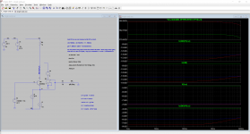
2) I dramatically simplified the simulation schematics : I just keep one emitter follower transistor biased at 1mA and an AC coupled load.
Results are ~ the same : ic(Q6)/v(b,e) variation is 55dB for 10k to 10Gohm load.
I also did some simple math in order to calculate ro. If no error, I have :
ro = vce/(ic - 38*Ic*vbe) ; Ic collector bias current (displayed on the scheme), 38*Ic ~ transconductance at 300K.
Results are on the attached plot : ro value is ~180kohm and is ~constant.
May be I missed something important, or don't understand something, but I don't see any problem with the model and the sim.
Attachments
2) I dramatically simplified the simulation schematics : I just keep one emitter follower transistor biased at 1mA and an AC coupled load.
Results are ~ the same : ic(Q6)/v(b,e) variation is 55dB for 10k to 10Gohm load.
I also did some simple math in order to calculate ro. If no error, I have :
ro = vce/(ic - 38*Ic*vbe) ; Ic collector bias current (displayed on the scheme), 38*Ic ~ transconductance at 300K.
Results are on the attached plot : ro value is ~180kohm and is ~constant.
May be I missed something important, or don't understand something, but I don't see any problem with the model and the sim.
Herve
What you have nicely shown is that Ro = (Vaf-Vce)/Ic. In your case with Vce ca 24V and Ic = 1mA this gives a value for the early voltage Vaf of 182.
Had you used 37.5 instead of 38, you would have calcultated a value of 168 Volt for Vaf, exactly what's in the BC550C model.
But Ro itself is not under discussion, it was just the suspicion that Ro was responsible for the drop in ic/vce at increasing load value, but that appears not to be the case after having taken Ro out of the equation.
Hans
1) It would be great if people -who claims not to declare or continue a flame war- avoids this kind of remark. The "other camp" is not composed of believers.
Herve, I meant nothing derogatory by the the "other camp" remark. In fact, I used it as a sign of respect. I'm sorry that you interpreted it as mean-spirited. That was not my intent.
Just remember - the rest of us belong to a "camp" too. And it's still a valid question - why does the existence of voltage feedback mean that there can be no current feedback? I haven't heard an explanation for this, only a repeated assertion that there is "voltage feedback." And yet I know of no one in "my" camp who denies this. Certainly Middlebrook sees elements of both.
"Other camp" is not a problem.
It's just that you said, more than one time, that we -other camp- only think about a pure voltage feedback.
It is not true. I said the contrary in post #963.
Herve
What you have nicely shown is that Ro = (Vaf-Vce)/Ic. In your case with Vce ca 24V and Ic = 1mA this gives a value for the early voltage Vaf of 182.
Had you used 37.5 instead of 38, you would have calcultated a value of 168 Volt for Vaf, exactly what's in the BC550C model.
I don't think so.
The upper plot of my sims calculate a resistor which sees an AC voltage vce and traversed by an AC current which is the total collector AC current minus the "transconductance AC current" g*vbe.
This almost constant resistor is entirely compatible with the observed behaviour.
I also sim with increased value of Vaf, crazy values shows ic/vbe almost constant.
It is responsible.But Ro itself is not under discussion, it was just the suspicion that Ro was responsible for the drop in ic/vce at increasing load value, but that appears not to be the case after having taken Ro out of the equation.
Hans
I am afraid your Ro cancelling doesn't work correctly.
I simulated both versions Non Inverting and Inverting and Keantoken, you are absolutely right.For those not following completely, this explains everything. Notice Hans has replaced the entire Diamond follower with the VBIC transistor. Since the Early effects cancel in a Diamond follower, changing one transistor to another model will cause a mismatch. The resulting transverse currents become a confounder. Therefore in an honest comparison the whole Diamond follower needs to use the new models.
Also notice that the simulation reports much lower than the 37mS we predict for Gm just based on Ic. This is because as the current load disappears, the voltage gain of a transistor does not go infinite. Early effect limits it to a certain value.
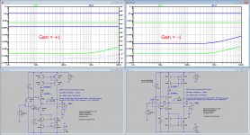
In a non-inverting amplifier the input voltage acts as a voltage load, since a transistor has no knowledge of ground. It just knows that Vce is changing. Therefore change to inverting input and the Gm behaves as predicted.
In both versions Ic(Q6) varies roughly the same 88dB when changing Rload from 1 to 1e10.
In the inverting version V(b,e) changes in exactly the same ratio as the Ic, causing Ic(Q6)/V(b,e) to stay constant at ca 37m.
However in the non inverting version V(b,e) drops only 40dB with Rload going from 1 to 1e10, causing Ic(Q6)/V(b,e) to drop by 48dB instead of
staying at 37m.
There is of course a logic explanation, but I'm still struggling finding it.
Hans
Attachments
Wow, that's something I have to respond to.I am afraid your Ro cancelling doesn't work correctly.
If not, please tell me what's wrong.
Hans
I simulated both versions Non Inverting and Inverting and Keantoken, you are absolutely right.
In both versions Ic(Q6) varies roughly the same 88dB when changing Rload from 1 to 1e10.
In the inverting version V(b,e) changes in exactly the same ratio as the Ic, causing Ic(Q6)/V(b,e) to stay constant at ca 37m.
However in the non inverting version V(b,e) drops only 40dB with Rload going from 1 to 1e10, causing Ic(Q6)/V(b,e) to drop by 48dB instead of
staying at 37m.
There is of course a logic explanation, but I'm still struggling finding it.
Hans
In inverting mode, Vce is almost constant.
Wow, that's something I have to respond to.
If not, please tell me what's wrong.
Hans
I think the arbitrary source doesn't work as you want in ac .
"Other camp" is not a problem.
It's just that you said, more than one time, that we -other camp- only think about a pure voltage feedback.
It is not true. I said the contrary in post #963.
Here is your statement from 963:
No, because if you change Rg, you change the open loop gain, so the OLG will change.
Why not thinking there is space between pure current feedback and pure voltage feedback ?
Why not thinking there is space between pure current feedback and pure voltage feedback ?
I don't know how to interpret this. Are you saying that a CFA employs both current and voltage feedback? If so, then we agree here. So what is the dispute about?
By the way, does forr agree? (Not your responsibility to speak for forr, I know.)
Please be so kind to prove it.I think the arbitrary source doesn't work as you want in ac .
Thinking is not good enough.
Hans
Please be so kind to prove it.
Thinking is not good enough.
Hans
Hans,
You can't reverse the demand of evidence.
Just another assumption, the opposite is true.In inverting mode, Vce is almost constant.
Hans
Attachments
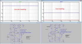
In inverting mode, Vce is almost constant.
Jesus guys, how many times needs this fact be repeated?
In an AC simulation, using the hybrid pi BJT model, r0 is not modelled as a vce depending conductance, but has a fixed value, depending on VAF and Vce (the bias point). ro and the load are essentially defining a current divider. I suspect that for very small conductances like 10^-10 numerical issues are occurring.
Vce is always constant, while the small signal ac vce variation is irrelevant. The BJT will never saturate or block, even for absurd values of vce amplitude. Just apply 1kV at the input of your ac simulation and watch the output scaling perfectly. Don't get fooled by the transistor symbol, usually associated with a nonlinear element. The AC BJT model is perfectly linear.
Spice AC simulations are essentially the simulation of a passive network containing ideal VCCSs.
Last edited:
Just another assumption, the opposite is true.
Hans
The opposite of what ?
You show exactly what I say.
Jesus guys, how many times needs this fact be repeated?
In an AC simulation, using the hybrid pi BJT model, r0 is not modelled as a vce depending conductance, but has a fixed value, depending on VAF and Vce (the bias point). ro and the load are essentially defining a current divider. I suspect that for very small conductances like 10^-10 numerical issues are occurring.
Vce is always constant, while the small signal ac vce variation is irrelevant. The BJT will never saturate or block, even for absurd values of vce amplitude. Just apply 1kV at the input of your ac simulation and watch the output scaling perfectly. Don't get fooled by the transistor symbol, usually associated with a nonlinear element. The AC BJT model is perfectly linear.
Spice AC simulations are essentially the simulation of a passive network containing ideal VCCSs.
I should have written "vce" instead of "Vce".
I apologize for that.
Still try to take the strong inference of what I write despite my bad English and typo.
Just another assumption, the opposite is true.
Hans
Hi Hans, sorry to bother, could you please give labels to N005 and N006?
Hi Chris,Hi Hans, sorry to bother, could you please give labels to N005 and N006?
We were discussing vce so V(N005) and V(N006) are both V(c).
Hans
I have made another Sim where the effect Ro in the BC550C/BC560C model has been eliminated by placing a current source par. to Ro, generating an exact opposite current.
By meticulously tuning in finding the Early voltages A and B for both transistors, I get the image below.
I think now the effect of Ro has been eliminated, it becomes quite obvious that Ro is not the cause of measuring different values for gm at differen values for Rload.
Hans
HI Hans,
I went back to take a look at your ro-cancelling post 2153. In the following, VCE and B are DC voltages and vbe and vce are AC voltages. Ic has AC and DC components, while IC is a DC current.
Let’s consider the modification of the BC560C. For small signal operation, I believe we can assume that there is a transconductive, an Early and an unknown (X) contribution to the unmodified transistor current. The Early current (vce/ro) is what you are trying to cancel:
Ic = IC + gm vbe +vce/ro + X
Adding your compensatory current source to the transistor, the total current is
It = Ic [ 1 + (VCE + vce) / ( B - (VCE + vce )) ] = Ic [ 1 + (24 + vce) / (138 - vce) ]
Some Questions:
Doesn’t this change the DC bias current and therefore gm?
Doesn’t this multiply all transistor currents by an AC signal which is a function of vce?
The only way I see to cancel vce/ro is if the term in the square brackets were zero, and it’s not. (And if it were, it would cancel everything!)
Wouldn’t a cancellation of the AC portion of the Early current be more appropriately accomplished by replacing the current source with a large capacitor in series with a negative resistance? LTSpice allows negative resistors.
I welcome your thoughts.
- Home
- Amplifiers
- Solid State
- Current Feedback Amplifiers, not only a semantic problem?