Thanks for the help with the led matching 🙂
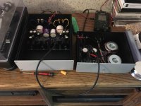
I powered up my build of Salas’s phono preamp yesterday (56dB configuration with FSP dual mono power supply) and biased it per the build guide. At moderate volumes all seemed well. I didn’t notice any hum or other problems, and it sounded pretty good (midrange was a bit recessed, but I am also using a brand new cartridge that needs to be broken in).
At higher volumes, I have 60Hz hum and also noticed that I was pulling in a local FM radio station. The hum and the radio “reception” can be changed by repositioning either the input or the output RCA cables. I also observed that if I hold my hand in close proximity to the preamp boards, without touching them, the hum increases, and if I touch the large red 100 pF input capacitors the hum on that channel increases.
For trouble shooting I have tried the following:
1) Removed the preamp input RCA cables - result: no change
2) Removed the turntable ground wire - result: no change
3) Changed position of the DC power cables (cables between the power supply and preamp) - result: increased or decreased hum changing the power wiring eliminated this effect see #7
4) Changed position of the output RCA cables - result: reduce or increase hum, increased radio “reception”. (Raising cables increases reception)
5) Plugged Power Supply into a different outlet - result: no change
6) Changed Output RCA cables from diy Mogami coax cables to cheap, generic RCA cables - result: no change
7) Changed from 2 independent power cables from power supply to preamp to single star quad shielded microphone cable (as suggested in the build guide) result: somewhat less hum, hum not changed by moving the power cable as was previously noted.
The hum and radio reception are the same with the preamp cover on or off (except I can’t get my hand near enough to the boards to create hum that way if the cover is on)
I am thinking of trying the following options for trouble shooting, but would really like other suggestions:
a) Replace large 100pF Clarity Cap CMR input capacitors with some Mundorf MKP’s of the same value.
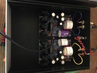
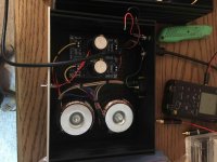
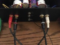
b) Relocate input and output RCA jacks to keep both inputs and outputs together (currently separated to minimize internal wire routing length, see photo)
Note: photos show the star quad power cable used in trouble shooting - this will be replaced with a more permanent solution later.
I powered up my build of Salas’s phono preamp yesterday (56dB configuration with FSP dual mono power supply) and biased it per the build guide. At moderate volumes all seemed well. I didn’t notice any hum or other problems, and it sounded pretty good (midrange was a bit recessed, but I am also using a brand new cartridge that needs to be broken in).
At higher volumes, I have 60Hz hum and also noticed that I was pulling in a local FM radio station. The hum and the radio “reception” can be changed by repositioning either the input or the output RCA cables. I also observed that if I hold my hand in close proximity to the preamp boards, without touching them, the hum increases, and if I touch the large red 100 pF input capacitors the hum on that channel increases.
For trouble shooting I have tried the following:
1) Removed the preamp input RCA cables - result: no change
2) Removed the turntable ground wire - result: no change
3) Changed position of the DC power cables (cables between the power supply and preamp) - result: increased or decreased hum changing the power wiring eliminated this effect see #7
4) Changed position of the output RCA cables - result: reduce or increase hum, increased radio “reception”. (Raising cables increases reception)
5) Plugged Power Supply into a different outlet - result: no change
6) Changed Output RCA cables from diy Mogami coax cables to cheap, generic RCA cables - result: no change
7) Changed from 2 independent power cables from power supply to preamp to single star quad shielded microphone cable (as suggested in the build guide) result: somewhat less hum, hum not changed by moving the power cable as was previously noted.
The hum and radio reception are the same with the preamp cover on or off (except I can’t get my hand near enough to the boards to create hum that way if the cover is on)
I am thinking of trying the following options for trouble shooting, but would really like other suggestions:
a) Replace large 100pF Clarity Cap CMR input capacitors with some Mundorf MKP’s of the same value.
b) Relocate input and output RCA jacks to keep both inputs and outputs together (currently separated to minimize internal wire routing length, see photo)
Note: photos show the star quad power cable used in trouble shooting - this will be replaced with a more permanent solution later.
Attachments
If you short your RCA input signal to ground at the board, one side at a time, does it make a difference?
Is the input/output wire shielded?
Does L-R side share a common ground to the chassis, or each channel?
Is the input/output wire shielded?
Does L-R side share a common ground to the chassis, or each channel?
A snap-on ferrite clamp placed on the turntable leads will fix the RF reception problem.
ZCAT1325-0530A-BK TDK Corporation | Filters | DigiKey
Not touching the capacitors is a good way to not have that particular problem... 🙂
Move the PSU further from the phono stage, and for that matter, move the phono stage away from any transformers.
Scrape the anodizing off the chassis where it touches other panels or screws, try to make a good electrical connection between all panels of the chassis.
If you short your RCA input signal to ground at the board, one side at a time, does it make a difference?
Is the input/output wire shielded?
Does L-R side share a common ground to the chassis, or each channel?
Shorting the input of one channel to ground at the board significantly reduced both the hum and radio reception on that channel. I am not sure what this means for implementing a permanent solution.
Input and Output RCA cables are shielded.
L-R both have a common ground to the chassis (from the ground point on the board to a common point on the rear of the chassis (green wires with ring terminals in the pictures) I think this is what is suggested in the build guide? I also connect the phono ground wire to this point on the back of the chassis.
A snap-on ferrite clamp placed on the turntable leads will fix the RF reception problem.
ZCAT1325-0530A-BK TDK Corporation | Filters | DigiKey
Not touching the capacitors is a good way to not have that particular problem... 🙂
Move the PSU further from the phono stage, and for that matter, move the phono stage away from any transformers.
Scrape the anodizing off the chassis where it touches other panels or screws, try to make a good electrical connection between all panels of the chassis.
I still have RF reception even with the input RCA's disconnected, do you think the choke on the inputs would still be worth while?
Moving the PSU farther away ~2ft did not change the hum.
I will disassemble and scrape off paint/anodize to bond the chassis panels to see if this helps. And install the covers 😀
Thanks again for the quick response!
Shorting the input of one channel to ground at the board significantly reduced both the hum and radio reception on that channel. I am not sure what this means for implementing a permanent solution.
Input and Output RCA cables are shielded.
L-R both have a common ground to the chassis (from the ground point on the board to a common point on the rear of the chassis (green wires with ring terminals in the pictures) I think this is what is suggested in the build guide? I also connect the phono ground wire to this point on the back of the chassis.
I still have RF reception even with the input RCA's disconnected, do you think the choke on the inputs would still be worth while?
Moving the PSU farther away ~2ft did not change the hum.
I will disassemble and scrape off paint/anodize to bond the chassis panels to see if this helps. And install the covers 😀
Thanks again for the quick response!
Two things that may or may not help.
I grounded the shield of cabled on both ends. In my case I moved to Mogami 2 wire, where ground is shield. That helped.
Also, more off course. I grounded the TT to the power supply chassis. Similar build to yours. That reduced hum more. That may have more to do with my umbilical wire routing in my stereo cabinet than anything else.
Sounds like something, maybe the ground wire itself, is acting as an antenna. Not sure how to deal with it, than maybe playing with clip leads as connections in a few places (usually ground) to see if that makes anything better.
Grounding problems and hum stink, but they make us learn to troubleshoot for certain - or give up and hurl it all into the void.
Maybe something on how the two chassis are grounded together and a mains earth loop with the rest of the test system by the way? There are a couple 1 Ohm channels rails return resistors in the RAW DC board. Remove one of them to see what happens.
You could also try a small capacitor from the input RCA connector "ground" shell directly to the chassis (keep leads as short as possible).
Thanks for all the help! My preamp is now quiet enough that I consider it fully functional (no RF, and hum is on parity with the noise floor).
The changes that yielded an improvement were:
- internal wiring changed from shielded twisted pair to coax
- all phono preamp enclosure panels bonded to ground
- bundle input and output RCA cables and route in fixed location selected to minimize hum and RF pickup
I tried some of the other suggestions, but couldn't notice a change.
- removed 1 ohm channel rails resistor from RAW DC circuit
- checked for ground loop in other equipment (connected battery powered portable recorder directly to phono preamp outputs and still had hum at a similar level)
Thanks to all and Happy New Year!
PS: Would anyone enjoy listening to a short recording taken directly from the preamp output, or would that just be taking up space on the diyAudio server for little value?
Last edited:
Congratulations for solving the issues. What cartridge and TT you use? A recording is welcome.
Here are a couple audio clips that were recorded using my build of Salas' phono preamp design. My turntable is a stock Technics SL1200 MkII, with an Ortofon Quintet Blue MC cartridge (0.5mV output, nude elliptical stylus). Also - thanks to Salas for sharing this design, and to Tea-Bag for organizing the group buy🙂
Attachments
Here are a couple audio clips that were recorded using my build of Salas' phono preamp design. My turntable is a stock Technics SL1200 MkII, with an Ortofon Quintet Blue MC cartridge (0.5mV output, nude elliptical stylus). Also - thanks to Salas for sharing this design, and to Tea-Bag for organizing the group buy🙂
Just a moment to bring the HD600 phones and listen to your build
In all seriousness, think about that... That's this phonostage in a nutshell - It was immediately obvious to me that your setup is needing a bit of adjustment. Speaks volumes to the quality of the RIAA amplifier...
(If your tracking force is, in fact, at the upper end of the suggested amount, may I make a second guess and bet that you are aligned to baerwald on the stock arm?)
(If your tracking force is, in fact, at the upper end of the suggested amount, may I make a second guess and bet that you are aligned to baerwald on the stock arm?)
Noise is ok, tonal balance is ok, details are ok, obviously the build works well. So congrats for that. There's a bit inexpressive midrange and other things not so breathtaking that are rather the Quintet cart's characteristics or it could shine better with a closer look on set up as a TT & cart combo. But that's getting into SQ details of a system, your DIY work has succeeded 
*I used Foobar replay software and Sennheiser cans
*I used Foobar replay software and Sennheiser cans
Hmm this article says it can be bit recessed in the mids indeed, at least when compared to a more expensive Dynavector cart, but it also took enough hours of mechanical break in until it's opened up: [Review] Ortofon Quintet Blue
Try various loading too along rechecking VTF & geometry. Most MC carts play well around the 200 Ohm load mark in my experience.
Try various loading too along rechecking VTF & geometry. Most MC carts play well around the 200 Ohm load mark in my experience.
Thanks for taking time to listen and provide feedback. I don't have any other points of reference outside my own system so your feedback is very valuable! I used an Ortofon alignment protractor I don't know if this is Baerwald or not. I printed a couple new alignment protractors (Technics specific Baerwald and a Stevenson protractor) from Vinyl Engine today and will realign the cartridge in the next few days. I also ordered a digital VTF gauge to replace my cheap manual beam type gauge to improve my setup. The cartridge has about 3-4 hours total playing time, so hopefully the sound will improve as it breaks in. It is also very good to hear that the DIY efforts seem successful, one variable eliminated 🙂
Yes, that's Baerwald. Use the overhang gauge in the box and align the stock arm to Stevenson. Get the walls of the cartridge as parallel to the head shell as possible and set the distance of the stylus tip to the gauge. Works perfectly.
Stevenson on that arm will sound surprisingly better. Send another clip once it's set. 🙂
Stevenson on that arm will sound surprisingly better. Send another clip once it's set. 🙂
may I ask what did you use to capture those samples ?
I used a Tascam DR-100MKIII "Field Recorder" and recorded as 24 bit 192kHz .wav files and then trimmed down with some free editing software from Tascam. I really like this recorder, it is well made and has worked very well for me.
DR-100MKIII | OVERVIEW | TASCAM
I have a Zoom H2n handy recorder which is cheaper and does a good job in general, especially with its mics, but more detectable regarding line level recordings than some top of the line models of course, also not built as rugged as those.
By the way, how much C2+C2Y total capacitance you installed in the RIAA treble EQ section of your build?
By the way, how much C2+C2Y total capacitance you installed in the RIAA treble EQ section of your build?
- Home
- Source & Line
- Analogue Source
- Simplistic NJFET RIAA