Of course it not representative of a realistic amplifier.
This caricatural scheme is to demonstrate that "current on demand" is not inherent to so called CFA but only to those which have a diamond (or similar) input.
Of course yes.
Gain bandwidth independance is obtained by playing with Rg resistor.
You have the same result by playing with the emitter resistor in a LTP or a double diamond.
Double diamond VFA allows same slew rate as so called CFA.
This is not correct. When I talk about tweaks, I don’t mean playing with Rg. Your claim that constant GBW in VFA can be had by fiddling with Rg is also not correct.
If you step closed loop gain in a properly MC compensated VFA (which you have shown in your sim) it is constant GBW.
I would plot the loop gains and check that on the low gain version that your amplifier is stable. For an MC comp’d VFA the slope should be 20 dB/decade
Last edited:
"almost exactly equal" : excellent !
This is absolutly not a proof of current feedback but a simple application of Kirchhoff law on In- node.
That Kirchoff's nodal law applies is no falsification of current feedback. You might just as well say that it's just Kirchoff's loop law and there is no voltage feedback.
Rg current minus output stage current is fed back to the input stage. A simple examination of what the words mean support the claim of c.f. Then add Middlebrook's DIT to discover that current feedback typically exceeds voltage feedback in CFAs. It couldn't be simpler to conclude that there is current feedback. I do not argue that the existence of c.f. precludes the existence of v.f. But you argue that simply because v.f. exists, c.f. cannot. I have yet to see any justification from you for this assertion.
Current feedback cannot explain the ratio between "gm*Vbe" and "Vce/Ro" current in the input device. Voltage feedback does.
Voltage is key to the transconductively controlled current; Kirchoff nodal current law addresses the current balances between that current and the Rf, Rg and ro currents. Middlebrook is quite happy with both forms of feedbacks coexisting.
I wrote almost the same thing in that thread before knowing the existence of MDIT.
I don't know what you are implying.
You wrote "electron flow"
In many posts to you, I have carefully written "signal current" to exclude DC bias current. In this case, I was trying to be absolutely clear about the relative directions of current flows. Are you trying to play "gotcha" here? Do you really believe for a moment that I was implying that input stage DC bias current always flows through the feedback network? Give me a break and drop it.
See attached.
This is in no way a response to the quote you captured. I assume you now accept that vce/ro is not a voltage-controlled transconductance.
What are the criteria ? Who established it ? Who accepted it ?
You're asking about Middlebrook's DIT? I will make no effort to try to convince you of it. Reject it, and quite frankly, there's no reason for us to continue talking. So please finally answer the question that I have asked repeatedly: Do you accept or reject Middlebrook's DIT as a means of determining the relative amounts of current and voltage feedback?
See attached. Current on demand is not inherent in CFA.
Constant bandwidth is easy to obtain with VFA, as current on demand.
Just as you can enhance uA709/uA741 type VFAs to provide these features, you can create purposely degenerate, questionably valuable circuits from useful CFAs. If you didn't purposely cripple a CFA to no obvious purpose, current on demand and the other functions we talked about would be inherent. Can you show me a useful, commercially available CFA that doesn't have these features?
I have never disputed that "Constant bandwidth is easy to obtain with VFA, as current on demand." What is your point? I have stated only that it is not inherent.
Not true. With a single transistor whose base is (in+) and emitter is in(-), you have unidirectional current on demand. Not very useful, but it exists.This caricatural scheme is to demonstrate that "current on demand" is not inherent to so called CFA but only to those which have a diamond (or similar) input.
Gain bandwidth independance is obtained by playing with Rg resistor.
You have the same result by playing with the emitter resistor in a LTP...
Change the gain block portion of a VFA and of course you change these characteristics - you are re-designing the gain block! The CFA supports these characterics with no change in the gain block - just in the feedback network.
Playing with Rg is for the so called CFA. For VFA, I wrote many time that you have to play with emitter resistors.This is not correct. When I talk about tweaks, I don’t mean playing with Rg. Your claim that constant GBW in VFA can be had by fiddling with Rg is also not correct.
Not if I play with emitter resisotrs as I didIf you step closed loop gain in a properly MC compensated VFA (which you have shown in your sim) it is constant GBW.
I attached the .asc file.I would plot the loop gains and check that on the low gain version that your amplifier is stable. For an MC comp’d VFA the slope should be 20 dB/decade
Attachments
What does it mean ? What is the base of comparison to say that one is more than the other ? Is there a little of voltage feedback in current feedback?current feedback typically exceeds voltage feedback in CFAs.
Is there a little of voltage feedback in current feedback?
 You made my day
 Yes, always. And the other way around.
Sorry, this is not correct.
MC means the gain slope intercepts the ULGF at 20 dB/decade and the slope is constant right up to the open loop -3dB point. If you step the closed loop gain, the closed loop BW slope is constant at 20 dB/decade - gain and bandwidth are linked.
You can fiddle with the emitter resistors, all this does is reduce the open loop gain. In s correctly compensated MC amp, it will not change the slope of the gain beyond the -3dB BW.
I never said Kirchhoff falsify current feedback.That Kirchoff's nodal law applies is no falsification of current feedback. You might just as well say that it's just Kirchoff's loop law and there is no voltage feedback.
Rg current minus output stage current is fed back to the input stage. A simple examination of what the words mean support the claim of c.f. Then add Middlebrook's DIT to discover that current feedback typically exceeds voltage feedback in CFAs. It couldn't be simpler to conclude that there is current feedback. I do not argue that the existence of c.f. precludes the existence of v.f. But you argue that simply because v.f. exists, c.f. cannot. I have yet to see any justification from you for this assertion.
No. Rg current minus output stage current come from input stage.
I am not responsible of the fact that the input transistor collector current is entirely dependant of voltages applied on base, collector and emitter with well known relations.
Voltages are the key of the total transistor collector current.Voltage is key to the transconductively controlled current; Kirchoff nodal current law addresses the current balances between that current and the Rf, Rg and ro currents. Middlebrook is quite happy with both forms of feedbacks coexisting.
Kirchoff can't explain the ratio of the 2 components of collector current.
I don't understand, and I don't know what is "playing gotcha"In many posts to you, I have carefully written "signal current" to exclude DC bias current. In this case, I was trying to be absolutely clear about the relative directions of current flows. Are you trying to play "gotcha" here? Do you really believe for a moment that I was implying that input stage DC bias current always flows through the feedback network? Give me a break and drop it.
You have written "electron flow" and I think it is not correct. If I can't correct what you write, just tell me.
vce/ro is a current.This is in no way a response to the quote you captured. I assume you now accept that vce/ro is not a voltage-controlled transconductance.
I think I can say that I can connect a VCCS as its behaviour is the same as a resistor.
I don't know how you determine that as the impedance seen by the in- is the same in the 2 configurations of the tests.You're asking about Middlebrook's DIT? I will make no effort to try to convince you of it. Reject it, and quite frankly, there's no reason for us to continue talking. So please finally answer the question that I have asked repeatedly: Do you accept or reject Middlebrook's DIT as a means of determining the relative amounts of current and voltage feedback?
So I don't feel ready to accept MDIT as the ultimate judge delivering the label of current or voltage feedback or their ratio.
I have not to show you a commercially available so called CFA which have not the COD feature.Just as you can enhance uA709/uA741 type VFAs to provide these features, you can create purposely degenerate, questionably valuable circuits from useful CFAs. If you didn't purposely cripple a CFA to no obvious purpose, current on demand and the other functions we talked about would be inherent. Can you show me a useful, commercially available CFA that doesn't have these features?
You claim that all so called CFA have this feature, this include single input device so called CFA.
This is not true.
You have to prove that what you claim is true. It will be very hard.
My point is that constant bandwidth is not a real advantage of so called CFA vs VFA.I have never disputed that "Constant bandwidth is easy to obtain with VFA, as current on demand." What is your point? I have stated only that it is not inherent.
Unidirectional COD is not CODNot true. With a single transistor whose base is (in+) and emitter is in(-), you have unidirectional current on demand. Not very useful, but it exists.
Change the gain block portion of a VFA and of course you change these characteristics - you are re-designing the gain block! The CFA supports these characterics with no change in the gain block - just in the feedback network.
You change the gain block of the so called CFA as the open loop gain depends directly of the feedback network.
You can fiddle with the emitter resistors, all this does is reduce the open loop gain. In s correctly compensated MC amp, it will not change the slope of the gain beyond the -3dB BW.
Or you can fiddle with the feedback resistor. If the emitter resistor is not much smaller than the feedback resistor, that would modify both the closed loop gain and the open loop gain, and a little math will show the bandwidth will remain constant (if the amp is single pole compensated, like Miller). Here's a VFA acting as a CFA.
If the emitter resistor is much smaller than the feedback resistor, fiddling with the feedback resistor will change only the closed loop gain, and the bandwidth will follow GBW=constant (if the amp is single pole compensated, like Miller). Here's a CFA acting as a VFA.
Start with one, and morph it in the other one. Nothing to do with the "feedback type", it's an interesting property of a particular circuit topology.
His gains were >> greater than this.
Separately, step the closed loop gain over say 1 to 30 and you can see the constant GBW behavior. Picking a single outlier case (gain of c. 2) does not make CFA = VFA.
Separately, step the closed loop gain over say 1 to 30 and you can see the constant GBW behavior. Picking a single outlier case (gain of c. 2) does not make CFA = VFA.
His gains were >> greater than this.
Separately, step the closed loop gain over say 1 to 30 and you can see the constant GBW behavior. Picking a single outlier case (gain of c. 2) does not make CFA = VFA.
I don’t think a 1:30 ratio will show constant bandwidth, it’s too much, perhaps a 1:10 (the ratio depends also on the impedance seen in the input stage emitter).
But choose whatever ratio fancies you, the transition from constant bandwidth to constant GBW will happen anyway. You failed, dear Andrew, to address how the same amplifier can act as both a CFA and a VFA, and how is this morphing related to the “feedback type”. Don’t you think this property is related to the particular circuit topology (the feedback network affecting more (CFA) or less (VFA) both the closed loop gain and the open loop gain)?
BTW, did I say anything about a single outlier case? No, I said for closed loop gains of (say) 2...10 it acts as a CFA with constant bandwidth and for larger closed loop gains (say) 50...60 it acts as a VFA with constant GBW, both approximative, there is no clear cut.
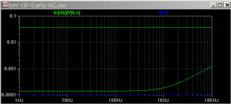
GP model Early effect anomaly
I think there is an anomaly created by the Gummel Poon BJT model used in SPICE.
Changing the BC550C in your post 1872 circuit Current Feedback Amplifiers, not only a semantic problem?
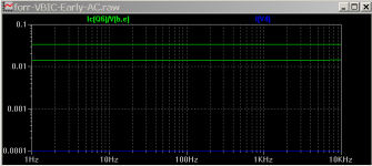
to VBIC model with exactly the same parameters gives a much reduced variation in the Ic(Q6)/V(b,e) ratio, was 300:1 with GP model, become 3:1 with VBIC. See plots attached, plus the circuit and models.
This huge difference must be from model equations differences. The Early effect is modeled differently in the VBIC to the 'standard' GP.
I don't know why there is still a residual variation with the VBIC. Maybe, as noted in the thread (below) that an inappropriate choice of Forward and Reverse parameters can lead to non-physical effects (since the GP model has two BJT's in anti-parallel to cover all 4 quadrants with one parameter set) Overunity transistors
More research is needed to get to the cause. (I include a .trans simulation in the attached and it shows the residual is present in the large signal and is not isolated to an AC simulation reporting issue).
My BC550C_V (VBIC) model has not been optimized, just a quick conversion using the mapping table in the VBIC "Text" document here http://www.designers-guide.org/VBIC/documents/VbicText.pdf I am not aware of any libraries for LTspice with VBIC transistors.
This relates to the query Post 1028, 26 Nov 2018, by CPaul Current Feedback Amplifiers, not only a semantic problem? and numerous follow-on's. I hope this apparent modelling anomaly settles this issue.
Thanks, CPaul, for raising it; it looks like we now have a good reason to convert to the VBIC model.
Cheers,
IH
Hi Chris, all,... please be so kind as to explain how a transistor in which the magnitudes of gm vbe and vce / ro are comparable can be considered to be a pure transconductor.
I think there is an anomaly created by the Gummel Poon BJT model used in SPICE.
Changing the BC550C in your post 1872 circuit Current Feedback Amplifiers, not only a semantic problem?
to VBIC model with exactly the same parameters gives a much reduced variation in the Ic(Q6)/V(b,e) ratio, was 300:1 with GP model, become 3:1 with VBIC. See plots attached, plus the circuit and models.
This huge difference must be from model equations differences. The Early effect is modeled differently in the VBIC to the 'standard' GP.
I don't know why there is still a residual variation with the VBIC. Maybe, as noted in the thread (below) that an inappropriate choice of Forward and Reverse parameters can lead to non-physical effects (since the GP model has two BJT's in anti-parallel to cover all 4 quadrants with one parameter set) Overunity transistors
More research is needed to get to the cause. (I include a .trans simulation in the attached and it shows the residual is present in the large signal and is not isolated to an AC simulation reporting issue).
My BC550C_V (VBIC) model has not been optimized, just a quick conversion using the mapping table in the VBIC "Text" document here http://www.designers-guide.org/VBIC/documents/VbicText.pdf I am not aware of any libraries for LTspice with VBIC transistors.
This relates to the query Post 1028, 26 Nov 2018, by CPaul Current Feedback Amplifiers, not only a semantic problem? and numerous follow-on's. I hope this apparent modelling anomaly settles this issue.
Thanks, CPaul, for raising it; it looks like we now have a good reason to convert to the VBIC model.
Cheers,
IH
Attachments
Middlebrook CFP (CFA) analysis
Thanks for your write-up/analysis. Good to have you back. Your observation is similar to mine. I posed a morphing thought experiment a while back (post 1115 Current Feedback Amplifiers, not only a semantic problem?).
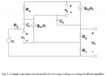
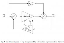
I was reading Middlebrook and the next morning a realization hit me that the forward transmission component in a CFA through Rf may be a key to differentiating the difference between CFA and a VFA. See attached Fig 2 of a CFP (CFA), and Fig 3, the block feedback diagram with the forward path. This shows the CFA is a more complicated than simple unidirectional blocks.
With a buffer between Rf and the CFA inverting input there is (ideally) no forward transmission component. I had previously not considered this feed-forward component in my analysis. One thing that can arise with a CFA is where the forward current can cancel the normal feedback current through Rf, and taken further, a phase reversal occurs in Rf. This was noticed by forr and CPaul in earlier posts.
Similarly, if Rg is removed then the phase in Rf is reversed.since the input stage current has to flows through Rf to the output. Usually with Rg in place the current flow is from the load through Rf. But again, with a buffer, the current in Rf can only flow from the load.
I thought this may be a useful distinguishing feature because morphing Betas (HFE's) of the buffer can't get past the one-way nature of a buffer. In the limit as the HFE is reduced to zero (just a diode) there is still one-way current. A direct piece of wire in place of the buffer (diode) makes a distinctly different type since forward current is then possible. Or have I got something wrong somewhere?
@forr: notice the name Middlebrook gives to the circuit Fig 2 is 'a typical 2-stage voltage-to-voltage feedback amplifier'. It's what we know as a CFP, which is a basic form of a CFA. Fig 3 is voltage difference feedback. His diagram may be from his earlier papers like 1989.
Cheers,
Syn08,...Start with one, and morph it in the other one. Nothing to do with the "feedback type", it's an interesting property of a particular circuit topology.
Thanks for your write-up/analysis. Good to have you back. Your observation is similar to mine. I posed a morphing thought experiment a while back (post 1115 Current Feedback Amplifiers, not only a semantic problem?).
I was reading Middlebrook and the next morning a realization hit me that the forward transmission component in a CFA through Rf may be a key to differentiating the difference between CFA and a VFA. See attached Fig 2 of a CFP (CFA), and Fig 3, the block feedback diagram with the forward path. This shows the CFA is a more complicated than simple unidirectional blocks.
With a buffer between Rf and the CFA inverting input there is (ideally) no forward transmission component. I had previously not considered this feed-forward component in my analysis. One thing that can arise with a CFA is where the forward current can cancel the normal feedback current through Rf, and taken further, a phase reversal occurs in Rf. This was noticed by forr and CPaul in earlier posts.
Similarly, if Rg is removed then the phase in Rf is reversed.since the input stage current has to flows through Rf to the output. Usually with Rg in place the current flow is from the load through Rf. But again, with a buffer, the current in Rf can only flow from the load.
I thought this may be a useful distinguishing feature because morphing Betas (HFE's) of the buffer can't get past the one-way nature of a buffer. In the limit as the HFE is reduced to zero (just a diode) there is still one-way current. A direct piece of wire in place of the buffer (diode) makes a distinctly different type since forward current is then possible. Or have I got something wrong somewhere?
@forr: notice the name Middlebrook gives to the circuit Fig 2 is 'a typical 2-stage voltage-to-voltage feedback amplifier'. It's what we know as a CFP, which is a basic form of a CFA. Fig 3 is voltage difference feedback. His diagram may be from his earlier papers like 1989.
Cheers,
Attachments
I don’t think a 1:30 ratio will show constant bandwidth, it’s too much, perhaps a 1:10 (the ratio depends also on the impedance seen in the input stage emitter).
But choose whatever ratio fancies you, the transition from constant bandwidth to constant GBW will happen anyway. You failed, dear Andrew, to address how the same amplifier can act as both a CFA and a VFA, and how is this morphing related to the “feedback type”. Don’t you think this property is related to the particular circuit topology (the feedback network affecting more (CFA) or less (VFA) both the closed loop gain and the open loop gain)?
BTW, did I say anything about a single outlier case? No, I said for closed loop gains of (say) 2...10 it acts as a CFA with constant bandwidth and for larger closed loop gains (say) 50...60 it acts as a VFA with constant GBW, both approximative, there is no clear cut.
I said step the gain - so by that I mean at say 2 or 3 dB intervals and plot them on the same graph.
At very low gains (3-6 dB) your amplifier response will probably show peaking (this what you would call GBW independence) and the response curves would seem to indicate CFA like performance. As the gain increases, you get the classic VFA GBW dependence.
I am willing to bet that at very low gains, the square wave response will be bad - overshoot, maybe ringing. To get rid of this, you will need to adjust the comp at very low gains. It would then be GBW dependent - so nothing to do with CFA like behavior.
If both input ports on a VFA are hi-z, how does a low feedback ratio give it CFA COD behsviour? It doesn’t. It’s just a badly comp’d VFA.
CFA’s do morph into VFA behavioral characteristics when you raise the (open) loop gain simply because you have to comp the thing to deal with the OPS pole. Here I talk about audio power amps - the issue seems less pronounced with IC’s because the OPS is usually very fast compared to a power amp but you still have a GBW independence sweet spot.
But, if I’m wrong, correct me and I’ll accept the error of my ways.
Last edited:
Sorry, this is not correct.
MC means the gain slope intercepts the ULGF at 20 dB/decade and the slope is constant right up to the open loop -3dB point. If you step the closed loop gain, the closed loop BW slope is constant at 20 dB/decade - gain and bandwidth are linked.
You can fiddle with the emitter resistors, all this does is reduce the open loop gain. In s correctly compensated MC amp, it will not change the slope of the gain beyond the -3dB BW.
Of course it is correct.
Playing with emitter resistors change the open loop gain and the product gain*bandwidth.
Emitter resistors play part of the role devoted to Rg in so called CFA.
Re in CFA’s is usually small compared to Rf and Rg because you want high gm (discrete power amps may be a special case for other reasons). Rf is used to compensate the amplifier and in IC types, you have no additional capacitance other than whatever is on the chip hung off the Tz node in the interests of preserving bandwidth. This is not the case with a VFA ( power amp) where you degenerate the LTP pair to ensure front end stage linearity. In an IC VFA, MC is used with the OL pole set at a few Hz so degeneration is not often used ( noise reasons as well).
Sorry, I don’t see CFA = VFA and never will. Two separate topologies that have some behavioural overlap under certain conditions wherein a CFA can morph towards VFA behaviour but nothing more.
Sorry, I don’t see CFA = VFA and never will. Two separate topologies that have some behavioural overlap under certain conditions wherein a CFA can morph towards VFA behaviour but nothing more.
What does it mean ? What is the base of comparison to say that one is more than the other ? Is there a little of voltage feedback in current feedback?
Not in, along with. Middlebrook's DIT answers your question.
I don't know how you determine that as the impedance seen by the in- is the same in the 2 configurations of the tests.
How about simply graphing the ratios of the inverting input voltages to their currents? They're identical. Enough proof?
So I don't feel ready to accept MDIT as the ultimate judge delivering the label of current or voltage feedback or their ratio.
OK, you've said it. I'm done here. Apart from all of the rest of it, the rejection of the obvious, inferring that I claim that DC current flows through the feedback network, if now MDIT is being questioned, there really is no basis for further discussion. I'm not going to take the time to even try to acquaint you with why you should accept it. Perhaps you and forr can form a study group to evaluate it.
Enjoy your beliefs.
Syn08,
Thanks for your write-up/analysis. Good to have you back. Your observation is similar to mine. I posed a morphing thought experiment a while back (post 1115 Current Feedback Amplifiers, not only a semantic problem?).
I was reading Middlebrook and the next morning a realization hit me that the forward transmission component in a CFA through Rf may be a key to differentiating the difference between CFA and a VFA. See attached Fig 2 of a CFP (CFA), and Fig 3, the block feedback diagram with the forward path. This shows the CFA is a more complicated than simple unidirectional blocks.
With a buffer between Rf and the CFA inverting input there is (ideally) no forward transmission component. I had previously not considered this feed-forward component in my analysis. One thing that can arise with a CFA is where the forward current can cancel the normal feedback current through Rf, and taken further, a phase reversal occurs in Rf. This was noticed by forr and CPaul in earlier posts.
Similarly, if Rg is removed then the phase in Rf is reversed.since the input stage current has to flows through Rf to the output. Usually with Rg in place the current flow is from the load through Rf. But again, with a buffer, the current in Rf can only flow from the load.
I thought this may be a useful distinguishing feature because morphing Betas (HFE's) of the buffer can't get past the one-way nature of a buffer. In the limit as the HFE is reduced to zero (just a diode) there is still one-way current. A direct piece of wire in place of the buffer (diode) makes a distinctly different type since forward current is then possible. Or have I got something wrong somewhere?
@forr: notice the name Middlebrook gives to the circuit Fig 2 is 'a typical 2-stage voltage-to-voltage feedback amplifier'. It's what we know as a CFP, which is a basic form of a CFA. Fig 3 is voltage difference feedback. His diagram may be from his earlier papers like 1989.
Ian, you are correct, and that's a great ideea that deserves a closer look. The two port model that I described (as serial input, shunt output feedback, covering both CFAs and VFAs) has, for the CFA topology, something that cannot be considered as "elegant". That is, while having the forward gain G21 dependent on the feedback network is certainly not a problem from a formalism perspective, if this dependence could be separated in a feed forward (or any other type) loop, that would be definitely one step forward. This new loop would actually control the CFA vs VFA behaviour and transition. The other small issue that your approach would solve is that right now, the forward gain block is not self consistent. A finite conductance G11 is required, otherwise the forward gain block is ill defined (once again, if considered in isolation). The input x1 buffer output impedance could play this role, but then again, if this could be moved in a feed forward loop, that would be much more elegant.
I'll take a closer look at this approach.
Last edited:
- Home
- Amplifiers
- Solid State
- Current Feedback Amplifiers, not only a semantic problem?