The numbers seem to add up. Not critical for my purposes I guess, but really nice to know. I can find 5ppm 1.93k 0.25W resistors. How would it compare to the 100ppm 0.5W trimmer currently installed in terms of stability? Voltage will of course be slightly less accurate... Thanks again!
Stability is not that critical in this case but fixed metal film resistors can be better for self noise than a typical trimmer. And no moving contact equals robust long term reliability of course. On the other hand you will lose any trimming ability if to check some other voltage level or to compensate for something.
The numbers seem to add up
Lets plug in a 10C delta for Vbe TC -2mV/C and red LEDS TC -1.5mV/C.
Cold Vref=(0.6Vx2)+(1945x0.002222)+(1.75x2)=9.021V
Warm Vref=(0.58Vx2)+(1945x0.002148)+(1.735x2)=8.807V
Yours was 9V cold and 8.72V warm. Give maybe some more degrees in your actual delta and differences in the VF of LEDS, my theory and your measured thermal settling drift do seem to compute 🙂
Stability is not that critical in this case but fixed metal film resistors can be better for self noise than a typical trimmer. And no moving contact equals robust long term reliability of course. On the other hand you will lose any trimming ability if to check some other voltage level or compensate for something.
Cool. I'll leave the trimmer in. It'll also prevent me from accidentally breaking off MOSFET legs as I did some heroic bending to make them fit. Also love the idea of being able to tweak voltage super easily, not that I anticipate doing it any time soon.😱
It would've been even nicer if I had a higher R1 and cooler build, but Soren did suggest 50% himself. It doesn't seem like this DAC should have peak power draws but it was reasonable to stay relatively cautious I think🙂
Btw I just realized that I forgot the 10R and 100nF in the ground loop breaker... Just ordered some and will add it in soon 😛
Lets plug in a 10C delta for Vbe TC -2mV/C and red LEDS TC -1.5mV/C.
Cold Vref=(0.6Vx2)+(1945x0.002222)+(1.75x2)=9.021V
Warm Vref=(0.58Vx2)+(1945x0.002148)+(1.735x2)=8.807V
Yours was 9V cold and 8.72V warm. Give maybe some more degrees in your actual delta and differences in the VF of LEDS, my theory and your measured thermal settling drift do seem to compute 🙂
That's crazy, thanks so much for the calculations!... I admit I was a bit confused why a linear regulator has quite significant voltage drift but this totally clears things up. And I was totally incapable of actually substituting your formula with all the right things.... Also 10C is definitely conservative here. 20 is probably closer to reality.
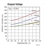
Btw, I was curious and checked out the LT3042 datasheet. Does this graph mean that it has a smaller temp drift?
Attachments
For say an actual 15C delta (locally on Q2 Q3 and LED1 LED2) the practical result would have been even closer with calculations.
That LT3042 graph is about its drop out voltage. Like the hotter it runs the more Vin-Vout difference it needs to stay in regulation. Such chips have compensated internal CCS for driving their external Vref setting resistor so don't expect any thermal settling for Vout to tell home about. Chips have the luxury of mutually compensating many internal parts in a well controlled super mini and enclosed surface. Those LT actually use the CCS and I/V on resistor Norton Vref principle for unity gain low noise Vref as the BiBs always used to have 🙂
As I wrote if you want much less thermal settling drift in UBiB there's the Zener alternative. But I consider their trimmer/resistor standard approach cleaner and softer. I could have used an op-amp buffered band-gap reference but those schemes use tons of feedback. The BiBs are a line of simplistic shunt regs with an alternative tone maybe but surely not designed for precision as the main goal. Like Class A amps, they need some time to thermally settle their bias.
Q2 Q3 might have been closer to 10-15. I was thinking about M1 M2... for some reason (not that anyone ever said the hottest chips are the culprit...) Like you said individual component characteristics vary so I'm perfectly satisfied with the theory.
What do you think is the main advantage of UltraBiB over LT3042 theoretically?... Makes me wonder why TI gave up on PCM1704. Maybe I should try the Delta-Sigma chips at some point also... It's really cute that almost everything in my build is discrete though - I told one of my friends about the build and he protested that there can be no DAC without a chip 🙂 There is a certain purity to the approach.
What do you think is the main advantage of UltraBiB over LT3042 theoretically?... Makes me wonder why TI gave up on PCM1704. Maybe I should try the Delta-Sigma chips at some point also... It's really cute that almost everything in my build is discrete though - I told one of my friends about the build and he protested that there can be no DAC without a chip 🙂 There is a certain purity to the approach.

Very low noise are both. Shunt vs series is one main thing. Shunt can also absorb current not only give. Also its CC biased. Does not carry the output load current changes to its input. Always pulls constant current from the reservoir. All changes refer to the output node.
Then its the output current and voltage range it can work which are times larger. Can be extended into several Ampere. Also its discrete and you can select parts.
Those very low noise chips are fairly recent, we mostly met classic three pin TO-220 ones in audio gear ten years ago when I made the first BiB. By the way, to meet their 1MHz PSRR spec those chips need very specific intricate layout as shown in their evaluation board papers that I don't know if its always feasible in gear they are to be put in where allowances must be made for other chips very close to them.
 Totally forgot this can work for a ton of other use cases with only minor (if any) adaptations. Very cool indeed. The theoretical differences probably mean more than I can understand at this point, but I can appreciate the fact that it's a different way of doing things alone.
That's very interesting background. Explains a lot - the low-noise chips do look close to the noise curves you posted as well as PSRR. I have no intention of going to the chips though 🙂 Btw, what's the reasoning behind the recommended 220uF C2 and not higher for even lower noise? Maybe it's somewhere in this thread and I could've missed it... Also, did you suggest at one point 10V +/- for Soekris?🙂 (maybe time to tweak that trimmer) I should maybe try to understand Soren's buffer circuit at some point...
Taking more time to reach Vout in start up but otherwise no problem other than fitting size in 63V for high output voltages for big preamps etc. See it as a soft start feature even.
A candidate nonetheless
Perhaps using a sledge hammer to drive a finishing nail but.....a privilege to have your sledge hammer to try. 😉
Taking more time to reach Vout in start up but otherwise no problem other than fitting size in 63V for high output voltages for big preamps etc. See it as a soft start feature even.
I see... But I doubt there's any noise left to be heard even with 220uF😛
Also, did you suggest at one point 10V +/- for Soekris?🙂 (maybe time to tweak that trimmer) I should maybe try to understand Soren's buffer circuit at some point...
It was DimDim's Soekris DAC build that we set 10V for with a proto-board UBiB test but he later explained here why, it had some parts pulled out or put in accounting for the difference or something like that.
It was DimDim's Soekris DAC build that we set 10V for with a proto-board UBiB test but he later explained here why, it had some parts pulled out or put in accounting for the difference or something like that.
In my dam1021 I've removed the on-board bridge rectifier, so my input DC voltage can be about 1.4V lower than the minimum manufacturer recommended DC voltage.
Not according to Soekris, but you might get better performance from your op-amps if you go a bit higher. I have no first hand experience in the matter.
Thanks! That was my impression too. I might trust Soren again on this one and stay with 9V - he knows the circuit and component better than I... I'm planning on using it to drive HD650 for a while. Maybe this wouldn't be that far behind a proper head amp?...
One quick question regarding the Teabag IRF+ kit parts. There is one light blue colored resistor and my DMM it shows as 000.3 ohms and I presume this is 330mOhms to be used for 'Rf' (low inductance). My DMM can show only single decimal so wasn't sure as I am building the Ultra BiB for my Soekris DAC to replace the 1.1 version.
Thanks
Thanks
- Home
- Amplifiers
- Power Supplies
- Salas SSLV1.3 UltraBiB shunt regulator