I think Hann window is also good, but you need > 8 cycles for a good plot, 16 is better.
Do you mean 8 cycles of the 1kHz? Or 8x more than what I have above for the time series as I have a pretty long one already (see below). I am not sure I am getting anything useful given my limited -130dB noise floor when using these other windows. I suppose it is good to see where the higher order components are, if I could see them.
Attachments
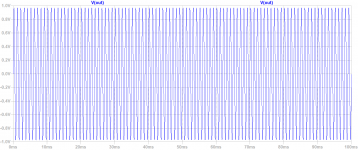
With a 1.1R drain resistor on the top MOSFET for 560mA bias current and using +/-18v rails, and dissipating about 10W per MOSFET, I am getting some pretty neat results driving 8Vpp into 8ohms (1Wrms) with 0.005% THD.
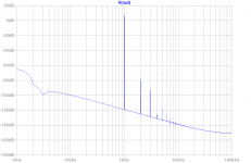
So, for a HPA, this is pretty nice that it can double as a low distortion fleawatt amp for high sensitivity speakers. Profile looks great too. Here is 8Vpp into 8ohms (Hanning window):

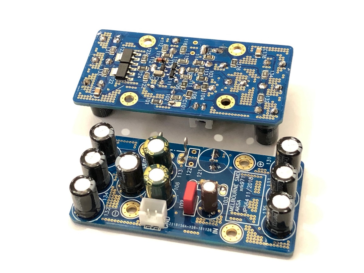
So, I think I am going to make this with the IRFP240/9240 bolted to a heatsink with flying leads to a small perf board containing the few ancillirary components, and then have this little preamp Melbourne board mounted next to it on the heatsink as well. Should be pretty compact and simple.
Here is Melbourne (SMT) version:
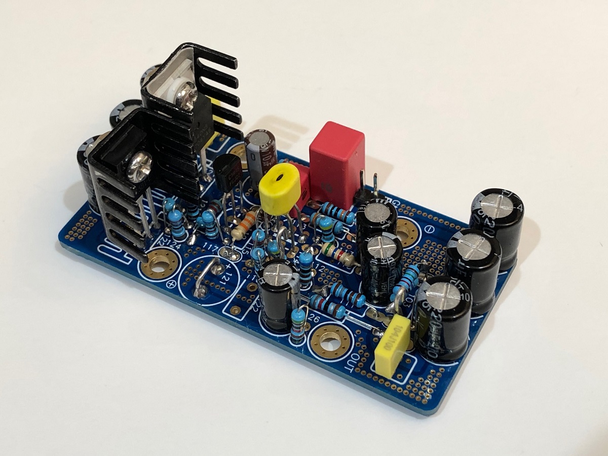
And here is the TH version - I might go TH this time:
Code:
Harmonic	Frequency	 Fourier 	Normalized	 Phase  	Normalized
 Number 	  [Hz]   	Component	 Component	[degree]	Phase [deg]
    1   	1.000e+03	4.031e+00	1.000e+00	   -0.15°	    0.00°
    2   	2.000e+03	2.045e-04	5.073e-05	   96.08°	   96.23°
    3   	3.000e+03	3.907e-05	9.691e-06	    7.36°	    7.51°
    4   	4.000e+03	1.306e-06	3.240e-07	 -157.69°	 -157.54°
    5   	5.000e+03	2.975e-06	7.380e-07	 -172.50°	 -172.35°
    6   	6.000e+03	1.529e-06	3.792e-07	  160.20°	  160.35°
    7   	7.000e+03	7.984e-07	1.981e-07	  172.56°	  172.71°
    8   	8.000e+03	9.002e-07	2.233e-07	 -170.31°	 -170.16°
    9   	9.000e+03	9.247e-07	2.294e-07	 -177.71°	 -177.56°
Total Harmonic Distortion: 0.005165%(0.005078%)
So, for a HPA, this is pretty nice that it can double as a low distortion fleawatt amp for high sensitivity speakers. Profile looks great too. Here is 8Vpp into 8ohms (Hanning window):
So, I think I am going to make this with the IRFP240/9240 bolted to a heatsink with flying leads to a small perf board containing the few ancillirary components, and then have this little preamp Melbourne board mounted next to it on the heatsink as well. Should be pretty compact and simple.
Here is Melbourne (SMT) version:
And here is the TH version - I might go TH this time:
Attachments
Last edited:
Just 8 -16 cycles of the sinewave. Distortion spectrum is also useful as indication of inherent smoothness of the transfer function. The point of windowing is to see below the noise floor with fewer periods on simulation.
Attachments
Here the QA401 result (Hann windowing) at 1Vpp. THD is around 0.034%.
Power supply is 12V with 4.7R bias resistor. Those little heat sinks get hot. I'm going to put on some better 'sinks and try it again at 15V

Power supply is 12V with 4.7R bias resistor. Those little heat sinks get hot. I'm going to put on some better 'sinks and try it again at 15V
Last edited:
I went ahead and built a TO220 version (albeit with IRF520 and 9520, as they were what I had in my parts bin).
Going to run it through the QA401, and I'll post results when I'm done 🙂
View attachment 722701
Is there any DC on the output? How stable is the offset? Just curious. Perhaps cap on the output for headphones protection.
Is there any DC on the output? How stable is the offset? Just curious. Perhaps cap on the output for headphones protection.
There is some DC, but using the trimpot I've got it down to a few mV. It takes a while to settle though, so a cap might be a good idea.
Some people are trying to avoid cap like a plague. But I have no problem to use them. Neither have Nelson. B1 and ACA have them on input and output and they sound great.
Ignore the plot in post 24! I forgot to connect the power supply bypass caps 😀. Looks much better now - THD down to 0.002%

Ignore the plot in post 24! I forgot to connect the power supply bypass caps 😀. Looks much better now - THD down to 0.002%
View attachment 722752
Nice! What was the dummy load impedance? This is 1Vpp?
Nice! What was the dummy load impedance? This is 1Vpp?
Yup, 1Vpp into 32 ohms. THD rises to 0.0065% at 1V RMS (2.828Vpp).
Last edited:
Ignore the plot in post 24! I forgot to connect the power supply bypass caps 😀. Looks much better now - THD down to 0.002%
View attachment 722752
Hi,
that made a difference - are you referring to 0.1uF bypass caps or something else?
Hi,
that made a difference - are you referring to 0.1uF bypass caps or something else?
1uF and 0.1uF decoupling caps. Bulk caps are around 10cm away.
Last edited:
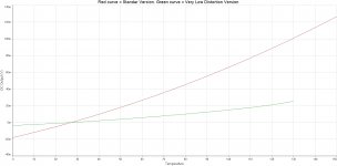
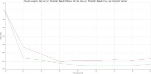
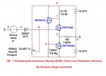
How many advances I have missed in my absence! Let me bring you a version for those whose inefficiency does not represent a problem. The version that I bring here, allows to greatly improve the distortion and the DC shift in the output. Only one parameter is reduced and it is the PSRR. Because it is a low power amplifier, a stabilized and well-filtered power supply voltage would be suggested.
The drastic reduction in the distortion is mainly due to the decrease in the current variation between drain and source of the IRFP240, above and below the static level, with the variation of the input signal 😉. THD is now 0,000292471 % at 1 KHz, 1 W, 4 ohms, 2 V RMS input / output signal.


The drastic reduction in the distortion is mainly due to the decrease in the current variation between drain and source of the IRFP240, above and below the static level, with the variation of the input signal 😉. THD is now 0,000292471 % at 1 KHz, 1 W, 4 ohms, 2 V RMS input / output signal.
Attachments
Last edited:

10K resistor can be replace by constant current source, example JFET constant current source which is simple. It look good at small signal analysis.
10K resistor can be replace by constant current source, example JFET constant current source which is simple. It look good at small signal analysis.
My sim.
Attachments

As this is 0dB buffer, what are others planning on using as the Preamp stage? With the Melbourne on separate +/-24v supply via a simple dual rail Mark Johnson/Prasi layout cap Mx and 10VA trafo, you can have a Preamp that can swing 40vpp in order to use the American Beauty (AmBeau) as a speaker amp. I have not run sims yet, but what is max voltage swing on AmBeau assuming circa 1.3amp bias and +/-24v rails? Can we get 40vpp for 25wrms into 8ohms?
Last edited:
- Home
- Amplifiers
- Solid State
- 1W - 7 Components American Beauty Buffer