Herve, for the circuit you provided, it can be demonstrated that Vout = I(in-)* Z(s). I(in-) flows through the input stage from the feedback network; I(in-) = I(R1) - I(R12). I(R12) comes from the output stage.
This satisfies the definition of feedback that I proposed earlier. What is your preferred definition of feedback?
You can of course, argue that I(in-) = (V(in+ - V(in-) ) / Z(in-) and that therefore this is voltage feedback. However, this adds unnecessary complexity, and does nothing to deny the case for current feedback.
I don't understand why it adds complexity. You can measure V(in+) - V(in-)
I am not sure my english level allows me to give a good definition.
Feedback : effect of a derived fraction of output on the input.
It recalls me that I have asked to gentlemen the definiton of :
Voltage feedback
Current feedback.
Of course, there is no open loop gain for signal on in+ inncase of current source on In-Consider the attached. We drive DC-stabilized CFAs in two ways:
(1) We apply a 1kHz voltage source to the (+) input and a 3kHz voltage source to the (-) input. These are of equal amplitude, and we see the difference of these signals at the CFA output. (The difference of the input signals multiplied by a factor of 1000 is displayed for reference.)
(2) We apply a 1kHz voltage source to the (+) input and a 3kHz current source to the (-) input. But only the 3kHz signal for the current source is apparent at the output. Oh, there is a 3kHz voltage difference between the inputs (no significant 1kHz component) - but this is only because Ohm's Law cannot be denied.
The CFA is responding to an applied current and ignoring an applied voltage.
I don't see how your comment applies to the quote it responds to.
The quote referred to (I assume) adding the resistor to the CFA -in, run THD sims and see.
But it's a "pure voltage" input but now the current (i.e. the -in sees the impedance connected to it) matters get the story straight.
I never said the the input impedance doesn't matter.
What is your definition of Voltage or Current feedback. ?
Can you give me an example of what can be done with a CFA and not with a VFA ?
The quote referred to (I assume) adding the resistor to the CFA -in, run THD sims and see.
Could be.
You're requiring an extra equation. And as I said, even if you do, it doesn't falsify current feedback.I don't understand why it adds complexity.
How do you use this to claim there is no current feedback?Feedback : effect of a derived fraction of output on the input.
For me, substitute the word "voltage" or "current" for the word "signal" in the definition I gave a few posts back.It recalls me that I have asked to gentlemen the definiton of :
Voltage feedback
Current feedback.
The reason is almost irrelevant; the fact of the phenomenon is not.Of course, there is no open loop gain for signal on in+ inncase of current source on In-
Does everybody agree on the reason why the voltage gain can be represented by the same expression (1+Rf/Rg) in both configurations VFA and CFA ?
Does everybody agree on the reason why the voltage gain can be represented by the same expression (1+Rf/Rg) in both configurations VFA and CFA ?
Reasons.
You're requiring an extra equation.
Actually, I was wrong. You don't need an extra equation for the voltage feedback paradigm. But current feedback is established by recognizing that:
V(out) = I(in-)*Z(s)
V(in-) = V(in+) - I(in-)*Z*(in-)
and the equation establishing that the input stage current is a linear combination of the output stage current and the feedback network ground current:
I(in-) = [ V(in-) - V(out) ] / Rf + V(in-) / Rg
Yes, because the CFA is responsive to the current fed back into its input. The VFA is not. What better proof of the effect of current feedback could you ask for?
Another case of 'staring at the answer and still not getting it'.
Jan
Does everybody agree on the reason why the voltage gain can be represented by the same expression (1+Rf/Rg) in both configurations VFA and CFA ?
The derivations for VFA and CFA are different because the operating principle is different. See various app notes that discuss this eg Ron Mancini in the TI OpAmp Applications manual or Hans Palouda’s app note (originally published by Nat Semi, now in the TI archives).
Last edited:
Originally Posted by forr
Does everybody agree on the reason why the voltage gain can be represented by the same expression (1+Rf/Rg) in both configurations VFA and CFA ?
I normally don't see Forr's posts but this was quoted by Bonsai.
Please note that the expression (1+Rf/Rg) is an approximation for everyday work but it is missing an error term that prevents it from being exact.
What error term? In the case of a VFA there is a voltage error term, the error voltage between the two inputs that is necessary to make the amp work at all.
In the case of a CFA there is a current error term, the error current into the inv input necessary to make the amp work at all.
Again, a case of staring at the answer and not ....
Jan
Does everybody agree on the reason why the voltage gain can be represented by the same expression (1+Rf/Rg) in both configurations VFA and CFA ?
I normally don't see Forr's posts but this was quoted by Bonsai.
Please note that the expression (1+Rf/Rg) is an approximation for everyday work but it is missing an error term that prevents it from being exact.
What error term? In the case of a VFA there is a voltage error term, the error voltage between the two inputs that is necessary to make the amp work at all.
In the case of a CFA there is a current error term, the error current into the inv input necessary to make the amp work at all.
Again, a case of staring at the answer and not ....
Jan
Well they're slowly starting to work out how feedback works, so there is progress 😎
Jan
😀
Originally Posted by forr
Does everybody agree on the reason why the voltage gain can be represented by the same expression (1+Rf/Rg) in both configurations VFA and CFA ?
I normally don't see Forr's posts but this was quoted by Bonsai.
Please note that the expression (1+Rf/Rg) is an approximation for everyday work but it is missing an error term that prevents it from being exact.
What error term? In the case of a VFA there is a voltage error term, the error voltage between the two inputs that is necessary to make the amp work at all.
In the case of a CFA there is a current error term, the error current into the inv input necessary to make the amp work at all.
Again, a case of staring at the answer and not ....
Jan
Yes, agreed Jan. It’s also important to note that the current in/out of the inverting input is highly frequency dependent. You can see this if you feed a fast rise/fall time square wave signal into a CFA and then plot an FFT of current into the inv input.
Old French proverb: "Not to look for Noon at 2 PM".
The reason is that the load due to the inverting input on the junction of Rf and Rg of the feedback network which defines the output voltage is very low in both cases.Does everybody agree on the reason why the voltage gain can be represented by the same expression (1+Rf/Rg) in both configurations VFA and CFA ?
Old French proverb: "Not to look for Noon at 2 PM".
The reason is that the load due to the inverting input on the junction of Rf and Rg of the feedback network which defines the output voltage is very low in both cases.

Forr, We already told you many posts back that at LF the error current into a CFA -in is very low and you can calculate that. The Vbe deltas are concomitantly very small and a function of the DC loop gain and Ro. This compares somewhat to the Vbe deltas you would see in a a VFA.
However, as pointed out many times, the situation changes dramatically as you increase frequency. Again, try the FFT experiment indicated in my previous post between a VFA and CFA.
There are so many proof points on CFA operation that I struggle to understand your dogged insistence that CFA = VFA, or that there is no such thing as a VFA.
Please don’t come back and give your standard ‘the voltage at the inv input = the non inv input therefor it must be a VFA’. That doesn’t cut it. The onus is on you to show that you can completely describe CFA operation with VFA principles and you have yet to do that.
Chris,Hans, I think I must ask you for your definition of feedback, because the statement you provided is not in accord with mine: "Current feedback" is not a "second point" in a circuit.
Thanks for reading my posting.
Could you explain what's wrong in your view in general with a two step feedback system , where the last step is the dominant one ?
The confusion may be that when talking about feedback, you are used to look at the output.
In case of the CFA you have to look at the IN- to see the pure current feedback and not at the output.
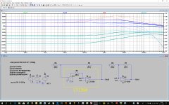
But please have a look at the image below. What's encircled in yellow is what is similar to a LT1364, a circuit that we call VFA, right ?
Now instead of using a LT1364, I used inside the yellow line a LT1395 plus an external buffer giving me the exact same functionality as the LT1364.
Outside the yellow line nothing changed so the set up must still be a VFA like with the LT1364.
But inside the yellow line there the LT1395, being a CFA.
Now the buffer and R3=Rf//Rg are left, and the LT1395 is connected directly to Rf and Rg.
And now all at the sudden the whole construction should become CFA instead of "a VFA with a CFA inside", despite both being 100% equal in FR etc.?
Not in my view. I see it as a two step feedback, VFA first and than CFA where the CFA has the lead. But I'm happy when you see it differently.
But at least we are both in agreement that as seen from IN- the CFA has pure and complete current feedback. 🙂
When looking at the plots you can see that the overall FR response and current to IN_ are 100% identical for both circuits.
The first being a VFA (with a CFA inside) an the second with just a CFA here shown with gains of resp 0dB, 20dB and 40dB.
Maybe this picture can tell more than a 1000 words. 😀
Attachments
I have read parts of this topic. VERY funny.
What a strange affair, where poetry, semantic and phantasms are mixed with some valuable technical inputs.
I cannot see major differences in audio between VFA and CFA, on my opinion. Both can lead to very similar good results.
Both are used from very long time and are totally academic.
The only real point is the impedance of the feedback path VS parasitic capacitance of the negative input in regard to phase turns at HF. So, we can achieve the same HF bandwidth with VFA if we set the input impedance low enough to have no phase turn at HF. That is not really good for the DC balance, if we keep the + input high enough to be usable in audio (~1K VS ~10k).
The other point is "current on demand" (expansive VS compressive) and its influence on the slew-rate. When the performance is >10 time better than the need, who cares ?
Having made a lot of comparisons between the two topologies, my personal preference goes to CFA with diamond input and some gain in the input stage to optimize noise and distortion. This said, some said that men prefer blondes ... but so many marry brunettes ;-)
I just like to add a point. In analog mixing desk pre-amps, CFA offers a major advantage in the "bus" lines. With VFA, the closed loop bandwidth decrease with the gain (the number of slices connected to one bus) there is an audible decrease of quality as you plug many lines in this phantom bus. While CFA keep the same performance apart noise due to the gain that affect anyway the two topologies.
And about the VFA/CFA names... who cares ?
Can one of you explain to me this anti CFA disease that affect some people here ?
Is it really witchcraft ?
Last edited:
Yes, agreed Jan. It’s also important to note that the current in/out of the inverting input is highly frequency dependent. You can see this if you feed a fast rise/fall time square wave signal into a CFA and then plot an FFT of current into the inv input.
Just as the error voltage in a VFA is highly frequency dependent (above the ol bandwidth) and for exactly the same reason.
Jan

Hi Hans, it's good to have a polite disagreement. This thread has seen too little of this sort of thing.
I believe that I have. I have provided what I think is a good definition of feedback. The two step approach that you describe does not fit it. I have invited you to suggest an alternative definition.
Well, no. I see no reason to focus more on the output in talking about feedback - VFA or CFA or fully differential feedback amplifiers. I generally see more of the "action" occurring at the inputs. The output generates a signal, but how that signal is applied at the inputs is more relevant to the type of feedback. Perhaps you are thinking of the historically and poorly named "current feedback" in which the load is part of the feedback network. But the circuit has no way of knowing that the designer considers the upper leg of a two component voltage divider to be a load. This kind of "current feedback" is indistinguishable from the voltage feedback due to the voltage divider in a standard VFA.
I grant you that the voltages and currents of the two circuits are identical. But I still have a problem with how you are using the definition of feedback, a general version of which I still request from you.
Rather than viewing the addition of E1 as part of the feedback network, I believe that it is more appropriate to see it as the new output stage. This view would be consistent with my definition of feedback.
But perhaps this all comes down to your general definition of feedback.
Could you explain what's wrong in your view in general with a two step feedback system , where the last step is the dominant one ?
I believe that I have. I have provided what I think is a good definition of feedback. The two step approach that you describe does not fit it. I have invited you to suggest an alternative definition.
The confusion may be that when talking about feedback, you are used to look at the output. In case of the CFA you have to look at the IN- to see the pure current feedback and not at the output.
Well, no. I see no reason to focus more on the output in talking about feedback - VFA or CFA or fully differential feedback amplifiers. I generally see more of the "action" occurring at the inputs. The output generates a signal, but how that signal is applied at the inputs is more relevant to the type of feedback. Perhaps you are thinking of the historically and poorly named "current feedback" in which the load is part of the feedback network. But the circuit has no way of knowing that the designer considers the upper leg of a two component voltage divider to be a load. This kind of "current feedback" is indistinguishable from the voltage feedback due to the voltage divider in a standard VFA.
But please have a look at the image below...
...Maybe this picture can tell more than a 1000 words. 😀
I grant you that the voltages and currents of the two circuits are identical. But I still have a problem with how you are using the definition of feedback, a general version of which I still request from you.
Rather than viewing the addition of E1 as part of the feedback network, I believe that it is more appropriate to see it as the new output stage. This view would be consistent with my definition of feedback.
But perhaps this all comes down to your general definition of feedback.
- Home
- Amplifiers
- Solid State
- Current Feedback Amplifiers, not only a semantic problem?