Here's it,Indr. Thanks for posting your build. If you get the chance we would like to see some measurements. Please dont be too defensive to comment as that can stop constructive ones too. It looks like something I could build. I only need a few watts for tweeter duty in actively filtered speakers. So I dont know if I should lover the
supply voltage. I will wait fo messurements
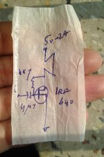
Drawn on tobacco paper, not promoting though
I'm low on resources, can't measure,
You better make one, it is very simple,
Hope this will pump few watts for your tweeter, higher freqiencies coming out very well
Don't know if you use preamp, but with pocket radio and walkman inputs, that offers high input impedance,
Great wattage,
But,
Volatge should not exceed 6v
At 9v 1a, voice coil heats up, at 12v 750a, you can light a matchstick !
I tried different supplies
Waiting for trying different mosfets
So far, irf 740 sounds damp, z44 less power
Will try 240 and more amps till I've to stop.
Hi. I think it's great that you are getting such performance from a simple circuit, less is more, can you post the schematic please?
I've posted the schema
Yesterday I did not have paper
Kindly check 👍
You did not complain about my post.
I feel left out!
Don't worry, if you like Mr. Ampere
I'll like you too
😝
Attachments
Indr. Thanks for posting your build. If you get the chance we would like to see some measurements. Please dont be too defensive to comment as that can stop constructive ones too. It looks like something I could build. I only need a few watts for tweeter duty in actively filtered speakers. So I dont know if I should lover the supply voltage. I will wait fo messurements
Don't even think about trying this with a tweeter, the thin voice coil would burn out very quickly and/or heat up so much that the coil melts and damages the cone.
Here's it,
Drawn on tobacco paper, not promoting though
I'm low on resources, can't measure,
You better make one, it is very simple,
Hope this will pump few watts for your tweeter, higher freqiencies coming out very well
Don't know if you use preamp, but with pocket radio and walkman inputs, that offers high input impedance,
Great wattage,
But,
Volatge should not exceed 6v
At 9v 1a, voice coil heats up, at 12v 750a, you can light a matchstick !
I tried different supplies
Waiting for trying different mosfets
So far, irf 740 sounds damp, z44 less power
Will try 240 and more amps till I've to stop.
Your schematic looks just like the one posted on post #2 where you said it was not correct. Can you explain how it is different?
Vs:
I have to give you this, never seen a schematic on a cigarette roller paper before. Perhaps a hint at a smoking voice could if running too much voltage 🙂
MOSFET will have 4v drop so about 1v across voice coil max. Most speakers can handle 1000mV dc offset but it dissipates about 1^2v/8R or 125mW.
Last edited:
Indr,
You have put up a rudimentary design, very similar to an early Nelson Pass Zen but without the refinements. You circuit is not even correctly drawn on a simulator, and when people reasonably suggest it is too simple, you came out punching.
Did you want praise for this? You really need to spend a little more time learning this craft before people will admire your circuits. And you must be gracious in criticism, it is the only way to learn, do not take it personally, this is not how you LEARN audio.
Hugh
Did I ask for anything? Praise or else?Indr,
rudimentary design... simulator..reasonably..too simple..punching.
praise? ...LEARN audio.
Hugh
I just put up something that works for me, for my need, and mentioned that someone can IMITATE this...followedby all the pros and cons of the scheme
I didn't follow the name you mentioned, I found some substances in the works done by some never known or forgotten names living exactly opposite land on earth from him.
Not all were reasonable though, action demands reaction.
I'm not selling audio, for my own purpose, I've learned quite with much more modifications from this simple design, addition of more elements, cascaded etc. Won't post anymore.
It was for minimalism lovers, who don't like to burn lamp and waste energy.
Last edited:
But indr, what you mentioned like power is just plainly wrong. So it seems reasonable to point out to others when they do this also, they will not get the results you say.
Basic honesty, no?
Jan
Basic honesty, no?
Jan
Your schematic looks just like the one posted on post #2 where you said it was not correct. Can you explain how it is different?
never seen a schematic on a cigarette roller paper before
Apology for that, But I did not mention the word wrong.
Well, there is a first for everything.
Last edited:
That basic honesty part was covered in subsequent replies, mentioning I'm low on resources as it is quite difficult to exactly measure the o/p power.But indr, what you mentioned like power is just plainly wrong. So it seems reasonable to point out to others when they do this also, they will not get the results you say.
Basic honesty, no?
Jan
I'm waiting for your measurements, how much are you getting?
Seems there's amazing power in simplicity, though )
You know, minimalism and that is OK - but you would get much more credit here at this place if you f.e. included an air-gap output transformer in your design...
All that means is those three points are connected together, not grounded as such
Apology in written issued
Have anyone made this, listening ?
How it sounds?
Can we concentrate on sound and profitability ?
You know, minimalism and that is OK - but you would get much more credit here at this place if you f.e. included an air-gap output transformer in your design...
O/p transformer is great thing, so we can increase input volts, safely but I tried with commonly available stuff, a 2a mobile charger is very common now with more mah in phone battery.
I just posted this with a vision 'Class A for all classes'
You can try, but I'm content with this, as long as I don't get any distortion.Then how about the more common capacitor coupling and using a current source?
To spread the benefits of class A you need a good speaker system though.
Will the ones made for chip amps work fine? I don't know.
I'm on way making one, made some progress.
Apology for that, But I did not mention the word wrong.
Well, there is a first for everything.
Half apology after I revisited the comment #2, the o/p sticker should have been made at the top of R load, not below so it could be confusing, just what happened.
No more comments in last one hour
may be all got lost to another world listening to this heavenly creation
Just before santa days
Hamlin's piper was very much real
He still exists 😉
Glad you are happy. Simple improvements have been mentioned, you don't seem very interested, there's not much more to say
This way has been tried and published by Mark Houston.
He uses only one MOSFET in a good way.
5W Single Ended Class A Power Amp From Mark Houston
DIY Class-A 2SK1058 MOSFET Amplifier Project
He uses only one MOSFET in a good way.
5W Single Ended Class A Power Amp From Mark Houston
DIY Class-A 2SK1058 MOSFET Amplifier Project
Nice to,see Mark's mention.
Exchanged messages with him on few occasions, about tramsformer supply vs smps ones, he is more into valves.
His zca is more is like zen amp, more robust, more voltage allowed, usual output driver position.
The voltage divider wastes quite an energy, the perennial put off for class A s.
You're the one of very few here with constructive suggestions.
I'm not against improvements, I only dislike complexities.
I've made some improvements too, with another transistor at,input, plus cascaded mosfets,with mixed results.
If you've few augmentations in mind, kindly upload a schematic or message me, I'll definitely make and listen.
👍
Exchanged messages with him on few occasions, about tramsformer supply vs smps ones, he is more into valves.
His zca is more is like zen amp, more robust, more voltage allowed, usual output driver position.
The voltage divider wastes quite an energy, the perennial put off for class A s.
Glad you are happy. Simple improvements have been mentioned, you don't seem very interested, there's not much more to say
You're the one of very few here with constructive suggestions.
I'm not against improvements, I only dislike complexities.
I've made some improvements too, with another transistor at,input, plus cascaded mosfets,with mixed results.
If you've few augmentations in mind, kindly upload a schematic or message me, I'll definitely make and listen.
👍
Half apology after I revisited the comment #2, the o/p sticker should have been made at the top of R load, not below so it could be confusing, just what happened.
For the reader's clarity:
In post #2, "RL" IS the speaker. Scratch the output tap, the only actual resistor is on the input. Correct?
The rolling paper drawing wins my prize for the coolest hand drawn schematic. (See, over here, people don't really use them for tobacco) What we need here is a Cheech & Chong smilie...
Last edited:
That basic honesty part was covered in subsequent replies, mentioning I'm low on resources as it is quite difficult to exactly measure the o/p power.
Ahh, but the nice thing is that even low on resources you can still use your brain ;-)
The absolute max power can easily be calculated from the schematic.
Maybe you missed it: post 21. About 0.6W theoretical max but we all know that in practice it will be less.
Jan
- Status
- Not open for further replies.
- Home
- Amplifiers
- Solid State
- My amazing simplest classA amp with mosfet 640