All of the above are available via this thread, please always do a search before asking for any tube SPICE model.
All of the above are available via this thread, please always do a search before asking for any tube SPICE model.
Thanks, it's good to know, but I couldnt find annything abou 6S33S or EF86
I hate to ask, because I've already asked for the 6AR6 models, but does anyone happen to have models of the 6DW5? It's a 9-pin mini from Sylvania, somewhat similar to a beefed up 6W6GT, but with higher zero-bias plate current, intended for use with the then-new (circa 1957) 110 degree deflection monochrome CRTs as a vertical deflection amp.
My main hobby is the restoration of vintage television sets, particularly color roundies from 1954 to 1959, and I have enough 6DW5s around to last me multiple lifetimes, yet nothing that uses them at the moment.
Links to the datasheets:
https://frank.pocnet.net/sheets/106/6/6DW5.pdf
https://frank.pocnet.net/sheets/127/6/6DW5.pdf
https://frank.pocnet.net/sheets/137/6/6DW5.pdf
Last edited:
Code:
**** 6DW5 ******************************************
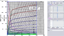
* Created on 12/04/2018 10:58 using paint_kip.jar
* [url=http://www.dmitrynizh.com/tubeparams_image.htm]Model Paint Tools: Trace Tube Parameters over Plate Curves, Interactively[/url]
* Plate Curves image file: 6dw5.png
* Data source link: <plate curves URL>
*----------------------------------------------------------------------------------
.SUBCKT 6DW5 P G2 G K ; LTSpice tetrode.asy pinout
* .SUBCKT 6DW5 P G K G2 ; Koren Pentode Pspice pinout
+ PARAMS: MU=10.7 KG1=308.88 KP=14.08 KVB=2578.94 VCT=0.00125 EX=1.218 KG2=683.76 KNEE=21.86 KVC=1.728
+ KLAM=3.2E-5 KLAMG=2.13E-4 KNEE2=20 KNEX=30 KNK=-0.044 KNG=0.006 KNPL=50 KNSL=11 KNPR=120 KNSR=29
+ CCG=14P CGP=0.5P CCP=9P RGI=2000.0
* Vp_MAX=400 Ip_MAX=600 Vg_step=5 Vg_start=10 Vg_count=11
* X_MIN=169 Y_MIN=12 X_SIZE=709 Y_SIZE=799 FSZ_X=1550 FSZ_Y=878 XYGrid=false
* Rp=1400 Vg_ac=20 P_max=11 Vg_qui=-15 Vp_qui=300
* showLoadLine=n showIp=y isDHP=n isPP=n isAsymPP=n isUL=n showDissipLimit=y
* showIg1=n isInputSnapped=y addLocalNFB=n
* XYProjections=n harmonicPlot=y dissipPlot=n
* UL=0.43 EG2=150 gridLevel2=n addKink=y isTanhKnee=y advSigmoid=n
*----------------------------------------------------------------------------------
RE1 7 0 1G ; DUMMY SO NODE 7 HAS 2 CONNECTIONS
E1 7 0 VALUE= ; E1 BREAKS UP LONG EQUATION FOR G1.
+{V(G2,K)/KP*LOG(1+EXP((1/MU+(VCT+V(G,K))/SQRT(KVB+V(G2,K)*V(G2,K)))*KP))}
RE2 6 0 1G ; DUMMY SO NODE 6 HAS 2 CONNECTIONS
E2 6 0 VALUE={(PWR(V(7),EX)+PWRS(V(7),EX))} ; Kg1 times KIT current
RE21 21 0 1
E21 21 0 VALUE={V(6)/KG1*ATAN((V(P,K)+KNEX)/KNEE)*TANH(V(P,K)/KNEE2)} ; Ip with knee but no slope and no kink
RE22 22 0 1 ; E22: kink curr deviation for plate
E22 22 0 VALUE={V(21)*LIMIT(KNK-V(G,K)*KNG,0,0.3)*(-ATAN((V(P,K)-KNPL)/KNSL)+ATAN((V(P,K)-KNPR)/KNSR))}
G1 P K VALUE={V(21)*(1+KLAMG*V(P,K))+KLAM*V(P,K) + V(22)}
* Alexander Gurskii screen current, see audioXpress 2/2011, with slope and kink added
RE43 43 K 1G ; Dummy
E43 43 G2 VALUE={0} ; Dummy
G2 43 K VALUE={V(6)/KG2*(KVC-ATAN((V(P,K)+KNEX)/KNEE)*TANH(V(P,K)/KNEE2))/(1+KLAMG*V(P,K))-V(22)}
RCP P K 1G ; FOR CONVERGENCE
C1 K G {CCG} ; CATHODE-GRID 1
C2 G P {CGP} ; GRID 1-PLATE
C3 K P {CCP} ; CATHODE-PLATE
R1 G 5 {RGI} ; FOR GRID CURRENT
D3 5 K DX ; FOR GRID CURRENT }
.MODEL DX D(IS=1N RS=1 CJO=10PF TT=1N)
.ENDS
*$
* The following triode model is derived from pentode model, see above.
* In the triode model, all spice parameters come directly from the pentode model, except for Kg1,
* which for triode-strapped pentodes is derived from pentode's Kg1, Kg2 and Kvc as
*
* 4Kg1Kg2 / ((2Kvc-Pi)(2Kg1+PiKg2))
**** 6DW5 ******************************************
* Created on 12/04/2018 10:58 using paint_kit.jar 4.7
* [url=http://www.dmitrynizh.com/tubeparams_image.htm]Model Paint Tools: Trace Tube Parameters over Plate Curves, Interactively[/url]
* Plate Curves image file: 6dw5.png
* Data source link: <plate curves URL>
*----------------------------------------------------------------------------------
.SUBCKT TRIODE_6DW5 1 2 3 ; Plate Grid Cathode
+ PARAMS: CCG=14P CGP=0.5P CCP=9P RGI=2000
+ MU=10.7 KG1=970.88 KP=14.08 KVB=2578.94 VCT=0.00125 EX=1.218
* Vp_MAX=400 Ip_MAX=600 Vg_step=5 Vg_start=10 Vg_count=11
* Rp=1400 Vg_ac=20 P_max=11 Vg_qui=-15 Vp_qui=300
* X_MIN=169 Y_MIN=12 X_SIZE=709 Y_SIZE=799 FSZ_X=1550 FSZ_Y=878 XYGrid=false
* showLoadLine=n showIp=y isDHT=n isPP=n isAsymPP=n showDissipLimit=y
* showIg1=n gridLevel2=n isInputSnapped=y
* XYProjections=n harmonicPlot=y dissipPlot=n
*----------------------------------------------------------------------------------
E1 7 0 VALUE={V(1,3)/KP*LOG(1+EXP(KP*(1/MU+(VCT+V(2,3))/SQRT(KVB+V(1,3)*V(1,3)))))}
RE1 7 0 1G ; TO AVOID FLOATING NODES
G1 1 3 VALUE={(PWR(V(7),EX)+PWRS(V(7),EX))/KG1}
RCP 1 3 1G ; TO AVOID FLOATING NODES
C1 2 3 {CCG} ; CATHODE-GRID
C2 2 1 {CGP} ; GRID=PLATE
C3 1 3 {CCP} ; CATHODE-PLATE
D3 5 3 DX ; POSITIVE GRID CURRENT
R1 2 5 {RGI} ; POSITIVE GRID CURRENT
.MODEL DX D(IS=1N RS=1 CJO=10PF TT=1N)
.ENDS
*$Attachments
I found the pentode strapped triode Mu of 4.3 in datasheet, so here is the remodel of 6dw5:
Code:
**** 6DW5 ******************************************
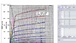
* Created on 12/04/2018 16:58 using paint_kip.jar
* [url=http://www.dmitrynizh.com/tubeparams_image.htm]Model Paint Tools: Trace Tube Parameters over Plate Curves, Interactively[/url]
* Plate Curves image file: 6dw5.png
* Data source link: <plate curves URL>
*----------------------------------------------------------------------------------
.SUBCKT 6DW5 P G2 G K ; LTSpice tetrode.asy pinout
* .SUBCKT 6DW5 P G K G2 ; Koren Pentode Pspice pinout
+ PARAMS: MU=4.3 KG1=21065.41 KP=10 KVB=0.1108 VCT=0 EX=2.131 KG2=42010.21 KNEE=23.18 KVC=1.693
+ KLAM=1.86E-5 KLAMG=2.556E-4 KNEE2=20 KNEX=30 KNK=-0.044 KNG=0.006 KNPL=50 KNSL=11 KNPR=120 KNSR=29
+ CCG=14P CGP=0.5P CCP=9P RGI=2000.0
* Vp_MAX=400 Ip_MAX=600 Vg_step=5 Vg_start=10 Vg_count=11
* X_MIN=169 Y_MIN=12 X_SIZE=727 Y_SIZE=799 FSZ_X=1550 FSZ_Y=878 XYGrid=false
* Rp=1400 Vg_ac=20 P_max=11 Vg_qui=-15 Vp_qui=300
* showLoadLine=n showIp=y isDHP=n isPP=n isAsymPP=n isUL=n showDissipLimit=y
* showIg1=n isInputSnapped=y addLocalNFB=n
* XYProjections=n harmonicPlot=y dissipPlot=n
* UL=0.43 EG2=150 gridLevel2=n addKink=y isTanhKnee=y advSigmoid=n
*----------------------------------------------------------------------------------
RE1 7 0 1G ; DUMMY SO NODE 7 HAS 2 CONNECTIONS
E1 7 0 VALUE= ; E1 BREAKS UP LONG EQUATION FOR G1.
+{V(G2,K)/KP*LOG(1+EXP((1/MU+(VCT+V(G,K))/SQRT(KVB+V(G2,K)*V(G2,K)))*KP))}
RE2 6 0 1G ; DUMMY SO NODE 6 HAS 2 CONNECTIONS
E2 6 0 VALUE={(PWR(V(7),EX)+PWRS(V(7),EX))} ; Kg1 times KIT current
RE21 21 0 1
E21 21 0 VALUE={V(6)/KG1*ATAN((V(P,K)+KNEX)/KNEE)*TANH(V(P,K)/KNEE2)} ; Ip with knee but no slope and no kink
RE22 22 0 1 ; E22: kink curr deviation for plate
E22 22 0 VALUE={V(21)*LIMIT(KNK-V(G,K)*KNG,0,0.3)*(-ATAN((V(P,K)-KNPL)/KNSL)+ATAN((V(P,K)-KNPR)/KNSR))}
G1 P K VALUE={V(21)*(1+KLAMG*V(P,K))+KLAM*V(P,K) + V(22)}
* Alexander Gurskii screen current, see audioXpress 2/2011, with slope and kink added
RE43 43 K 1G ; Dummy
E43 43 G2 VALUE={0} ; Dummy
G2 43 K VALUE={V(6)/KG2*(KVC-ATAN((V(P,K)+KNEX)/KNEE)*TANH(V(P,K)/KNEE2))/(1+KLAMG*V(P,K))-V(22)}
RCP P K 1G ; FOR CONVERGENCE
C1 K G {CCG} ; CATHODE-GRID 1
C2 G P {CGP} ; GRID 1-PLATE
C3 K P {CCP} ; CATHODE-PLATE
R1 G 5 {RGI} ; FOR GRID CURRENT
D3 5 K DX ; FOR GRID CURRENT }
.MODEL DX D(IS=1N RS=1 CJO=10PF TT=1N)
.ENDS
*$
* The following triode model is derived from pentode model, see above.
* In the triode model, all spice parameters come directly from the pentode model, except for Kg1,
* which for triode-strapped pentodes is derived from pentode's Kg1, Kg2 and Kvc as
*
* 4Kg1Kg2 / ((2Kvc-Pi)(2Kg1+PiKg2))
**** 6DW5 ******************************************
* Created on 12/04/2018 16:58 using paint_kit.jar 4.7
* [url=http://www.dmitrynizh.com/tubeparams_image.htm]Model Paint Tools: Trace Tube Parameters over Plate Curves, Interactively[/url]
* Plate Curves image file: 6dw5.png
* Data source link: <plate curves URL>
*----------------------------------------------------------------------------------
.SUBCKT TRIODE_6DW5 1 2 3 ; Plate Grid Cathode
+ PARAMS: CCG=14P CGP=0.5P CCP=9P RGI=2000
+ MU=4.3 KG1=83187.79 KP=10 KVB=0.1108 VCT=0 EX=2.131
* Vp_MAX=400 Ip_MAX=600 Vg_step=5 Vg_start=10 Vg_count=11
* Rp=1400 Vg_ac=20 P_max=11 Vg_qui=-15 Vp_qui=300
* X_MIN=169 Y_MIN=12 X_SIZE=727 Y_SIZE=799 FSZ_X=1550 FSZ_Y=878 XYGrid=false
* showLoadLine=n showIp=y isDHT=n isPP=n isAsymPP=n showDissipLimit=y
* showIg1=n gridLevel2=n isInputSnapped=y
* XYProjections=n harmonicPlot=y dissipPlot=n
*----------------------------------------------------------------------------------
E1 7 0 VALUE={V(1,3)/KP*LOG(1+EXP(KP*(1/MU+(VCT+V(2,3))/SQRT(KVB+V(1,3)*V(1,3)))))}
RE1 7 0 1G ; TO AVOID FLOATING NODES
G1 1 3 VALUE={(PWR(V(7),EX)+PWRS(V(7),EX))/KG1}
RCP 1 3 1G ; TO AVOID FLOATING NODES
C1 2 3 {CCG} ; CATHODE-GRID
C2 2 1 {CGP} ; GRID=PLATE
C3 1 3 {CCP} ; CATHODE-PLATE
D3 5 3 DX ; POSITIVE GRID CURRENT
R1 2 5 {RGI} ; POSITIVE GRID CURRENT
.MODEL DX D(IS=1N RS=1 CJO=10PF TT=1N)
.ENDS
*$Attachments
Hi, do you have any model for the EF86 as I found only equivalents but I dont trust the figures are exactly the same.
Regards, Victor
Regards, Victor
Hi, do you have any model for the EF86 as I found only equivalents but I dont trust the figures are exactly the same.
Regards, Victor
I used this model 2 years back on Tim Mellow OTL simulation posted numerous sim since, not sure if derived from original datasheet, so check it out.
Code:
.SUBCKT EF86 A S G K
 * Calculate reduction in mu when Vg < -3V
Emu             mu              0               VALUE={LIMIT{V(G,K),-3,999}+LIMIT{V(G,K)+3,-999,0}*0.714}
* Calculate contribution to cathode current
Eat             at              0               VALUE={0.636*ATAN(V(A,K)/15)}
Egs             gs              0               VALUE={LIMIT{V(S,K)/27.5+V(mu)*1.32+1,0,1E6}}
Egs2            gs2             0               VALUE={PWRS(V(gs),1.5)}
Ecath           cc              0               VALUE={V(gs2)*V(at)}
* Calculate anode current
Ga              A               K               VALUE={5.83E-4*V(cc)}
* Calculate screen current
*
Escrn           sc              0               VALUE={V(gs2)*(1.1-V(at))}
Gs              S               K               VALUE={0.5E-3*V(sc)}
* Capacitances
Cg1             G               K               3.8p
Cak             A               K               5.3p
Cg1a            G               A               0.05p

.ENDS
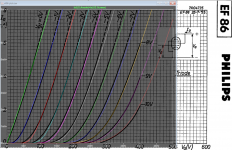
eventualy, shall I trust the US equivalent data?Hmm, it appears to be quite a bit off from the Philips datasheet...
Thanks for verification.
Here is another one based on Svetlana datasheet, please do comparison before use.
6B4G PP amp based on Mullard toplogy: a mod to Eico HF-60
Here is another one based on Svetlana datasheet, please do comparison before use.
6B4G PP amp based on Mullard toplogy: a mod to Eico HF-60
Code:
** EF86  as TRIODE ******************************************************
 * Created on Mon Aug 02 13:20:50 PDT 2004 using tube.model.finder.PaintKIT
 * data URL: [url=http://www.svetlana.com/graphics/products/pdf/EF86.pdf]404 - File or directory not found.[/url]
 *--------------------------------------------------
 .SUBCKT TRIODE_EF86 1 2 3 ; P G K ;
 + PARAMS: CCG=3P  CGP=4.4P CCP=4.9P RGI=2000
 + MU=37.2960 EX=1.3929 KG1=2010.0 KP=318.0 KVB=15.0 VCT=1.104
 *--------------------------------------------------
 E1 7 0 VALUE={V(1,3)/KP*LOG
 +  (1+EXP(KP*(1/MU+(VCT+V(2,3))/SQRT(KVB+V(1,3)*V(1,3)))))}
 RE1 7 0 1G
 G1 1 3 VALUE={(PWR(V(7),EX)+PWRS(V(7),EX))/KG1}
 RCP 1 3 1G   ; TO AVOID FLOATING NODES
 C1 2 3 {CCG} ; CATHODE-GRID
 C2 2 1 {CGP} ; GRID=PLATE
 C3 1 3 {CCP} ; CATHODE-PLATE
 D3 5 3 DX ; FOR GRID CURRENT
 R1 2 5 {RGI} ; FOR GRID CURRENT
 .MODEL DX D(IS=1N RS=1 CJO=10PF TT=1N)
 .ENDS
*$No, unfortunately, that one is no good for EF86 either...eventualy, shall I trust the US equivalent data?
So, what shall we do for?No, unfortunately, that one is no good for EF86 either...
There appears to be a scaling issue with the models vs. the datasheet, the quick fix is to lower the screen grid voltage, e.g., 130V instead of 140V, bring the curves quite close to the datasheet. But in the actual circuit, you may need to make further adjustment. In any case, there are large variations in the tube parameters due to the tolerance of the manufacturing process, so the tubes that you have may not be that close to the datasheet.
Here is another model called pf86_200, think it's EF86:
The uTracer, a miniature Tube Curve Tracer / Tester.
I commented out *C5 below as don't have G1G2 capacitance, fill in the other capacitance from datasheet. Mu is closed to 40 and 37.5 the other model.
The uTracer, a miniature Tube Curve Tracer / Tester.
I commented out *C5 below as don't have G1G2 capacitance, fill in the other capacitance from datasheet. Mu is closed to 40 and 37.5 the other model.
Code:
****************************************************
.SUBCKT pf86_200 1 2 3 4 ; A G2 G1 C;
*      Extract V1.030
* Model created:  5-Jan-2014
X1 1 2 3 4 PentodeD  MU= 40.9 EX=1.322 kG1= 668.7 KP= 354.6 kVB =  2001.1 kG2= 3941.2
+ Ookg1mOokG2=.12E-02 Aokg1=.94E-07 alkg1palskg2=.12E-02 be=   .28 als=  4.23 RGI=2000
+ CCG1=0.0P  CCG2 = 0.0p CPG1 = 0.0p CG1G1 = 0.0p CCP=0.0P  ;
.ENDS

****************************************************
.SUBCKT PentodeD 1 2 3 4; A G2 G1 C
RE1  7 0  1MEG    ; DUMMY SO NODE 7 HAS 2 CONNECTIONS
E1 7 0 VALUE=
+{V(2,4)/KP*LOG(1+EXP(KP*(1/MU+V(3,4)/SQRT(KVB+V(2,4)*V(2,4)))))}
E2   8 0 VALUE = {Ookg1mOokG2 + Aokg1*V(1,4) - alkg1palskg2/(1 + be*V(1,4))}
G1   1 4  VALUE = {0.5*(PWR(V(7),EX)+PWRS(V(7),EX))*V(8)}
G2   2 4 VALUE = {0.5*(PWR(V(7),EX)+PWRS(V(7),EX))/KG2 * (1+ als/(1+be*V(1,4)))}
RCP  1 4  1G      ; FOR CONVERGENCE             A  - C
C1   3 4  {CCG1}   ; CATHODE-GRID 1             C  - G1
C4   2 4  {CCG2}   ; CATHODE-GRID 2             C  - G2
*C5   2 3  {CG1G2}   ; GRID 1 -GRID 2            G1  - G2
C2   1 3  {CPG1}  ; GRID 1-PLATE                G1 - A
C3   1 4  {CCP}   ; CATHODE-PLATE               A  - C
R1   3 5  {RGI}   ; FOR GRID CURRENT            G1 - 5
D3   5 4  DX      ; FOR GRID CURRENT            5  - C
.MODEL DX D(IS=1N RS=1 CJO=10PF TT=1N)
.ENDS PentodeD
Last edited:
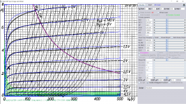
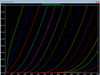
I finally paint one myself. Btw there is a bug in paint tool in "Advance Knee", but try to avoid it should be fine.
Code:
*[url=http://www.dmitrynizh.com/tubeparams_image.htm]Model Paint Tools: Trace Tube Parameters over Plate Curves, Interactively[/url]
* Plate Curves image file: ef86_PL.png
* Data source link: <plate curves URL>
*----------------------------------------------------------------------------------
.SUBCKT EF86_PL P G2 G K ; LTSpice tetrode.asy pinout
* .SUBCKT EF86_PL P G K G2 ; Koren Pentode Pspice pinout
+ PARAMS: MU=37.16 KG1=2341.97 KP=249.3 KVB=1251.59 VCT=0.00625 EX=1.289 KG2=3865.68 KNEE=5.029 KVC=1.696
+ KLAM=6.137E-8 KLAMG=2.1E-4   KNK=-0.044 KNG=0.006 KNPL=50 KNSL=11 KNPR=120 KNSR=29
+ CCG=3.8P CGP=0.05P CCP=5.3P RGI=2000.0
* Vp_MAX=500 Ip_MAX=8 Vg_step=0.5 Vg_start=0 Vg_count=20
* X_MIN=35 Y_MIN=14 X_SIZE=957 Y_SIZE=764 FSZ_X=1550 FSZ_Y=878 XYGrid=false
* Rp=1400 Vg_ac=20 P_max=1 Vg_qui=-4.75 Vp_qui=300
* showLoadLine=n showIp=y isDHP=n isPP=n isAsymPP=n isUL=n showDissipLimit=y
* showIg1=n isInputSnapped=y addLocalNFB=n
* XYProjections=n harmonicPlot=y dissipPlot=n
* UL=0.43 EG2=140 gridLevel2=n addKink=y isTanhKnee=n advSigmoid=n
*----------------------------------------------------------------------------------
RE1  7 0  1G    ; DUMMY SO NODE 7 HAS 2 CONNECTIONS
E1   7 0  VALUE=  ; E1 BREAKS UP LONG EQUATION FOR G1.
+{V(G2,K)/KP*LOG(1+EXP((1/MU+(VCT+V(G,K))/SQRT(KVB+V(G2,K)*V(G2,K)))*KP))}
RE2  6 0  1G    ; DUMMY SO NODE 6 HAS 2 CONNECTIONS
E2  6 0  VALUE={(PWR(V(7),EX)+PWRS(V(7),EX))} ; Kg1 times KIT current
RE21 21 0 1
E21  21 0 VALUE={V(6)/KG1*ATAN(V(P,K)/KNEE)} ; Ip with knee but no slope and no kink
RE22 22 0 1 ; E22: kink curr deviation for plate
E22  22 0 VALUE={V(21)*LIMIT(KNK-V(G,K)*KNG,0,0.3)*(-ATAN((V(P,K)-KNPL)/KNSL)+ATAN((V(P,K)-KNPR)/KNSR))}
G1   P  K  VALUE={V(21)*(1+KLAMG*V(P,K))+KLAM*V(P,K) + V(22)}
* Alexander Gurskii screen current, see audioXpress 2/2011, with slope and kink added
RE43 43 K 1G ; Dummy
E43  43 G2 VALUE={0} ; Dummy
G2   43 K  VALUE={V(6)/KG2*(KVC-ATAN(V(P,K)/KNEE))/(1+KLAMG*V(P,K))-V(22)}
RCP  P K  1G     ; FOR CONVERGENCE
C1   K G  {CCG}  ; CATHODE-GRID 1
C2   G P  {CGP}  ; GRID 1-PLATE
C3   K P  {CCP}  ; CATHODE-PLATE
R1   G 5  {RGI}  ; FOR GRID CURRENT
D3   5 K  DX     ; FOR GRID CURRENT }
.MODEL DX D(IS=1N RS=1 CJO=10PF TT=1N)
.ENDS
*$


* The following triode model is derived from pentode model, see above.
* In the triode model, all spice parameters come directly from the pentode model, except for Kg1,
* which for triode-strapped pentodes is derived from pentode's Kg1, Kg2 and Kvc as
*
*    4Kg1Kg2 / ((2Kvc-Pi)(2Kg1+PiKg2))

**** EF86_PL ******************************************
* Created on 12/04/2018 22:41 using paint_kit.jar 4.7
* [url=http://www.dmitrynizh.com/tubeparams_image.htm]Model Paint Tools: Trace Tube Parameters over Plate Curves, Interactively[/url]
* Plate Curves image file: ef86_PL.png
* Data source link: <plate curves URL>
*----------------------------------------------------------------------------------
.SUBCKT TRIODE_EF86_PL 1 2 3 ; Plate Grid Cathode
+ PARAMS: CCG=3.8P  CGP=0.05P CCP=5.3P RGI=2000
+ MU=37.16 KG1=8593.92 KP=249.3 KVB=1251.59 VCT=0.00625 EX=1.289
* Vp_MAX=500 Ip_MAX=8 Vg_step=0.5 Vg_start=0 Vg_count=20
* Rp=1400 Vg_ac=20 P_max=1 Vg_qui=-4.75 Vp_qui=300
* X_MIN=35 Y_MIN=14 X_SIZE=957 Y_SIZE=764 FSZ_X=1550 FSZ_Y=878 XYGrid=false
* showLoadLine=n showIp=y isDHT=n isPP=n isAsymPP=n showDissipLimit=y
* showIg1=n gridLevel2=n isInputSnapped=y
* XYProjections=n harmonicPlot=y dissipPlot=n
*----------------------------------------------------------------------------------
E1 7 0 VALUE={V(1,3)/KP*LOG(1+EXP(KP*(1/MU+(VCT+V(2,3))/SQRT(KVB+V(1,3)*V(1,3)))))}
RE1 7 0 1G  ; TO AVOID FLOATING NODES
G1 1 3 VALUE={(PWR(V(7),EX)+PWRS(V(7),EX))/KG1}
RCP 1 3 1G   ; TO AVOID FLOATING NODES
C1 2 3 {CCG} ; CATHODE-GRID
C2 2 1 {CGP} ; GRID=PLATE
C3 1 3 {CCP} ; CATHODE-PLATE
D3 5 3 DX ; POSITIVE GRID CURRENT
R1 2 5 {RGI} ; POSITIVE GRID CURRENT
.MODEL DX D(IS=1N RS=1 CJO=10PF TT=1N)
.ENDS
*$
Attachments
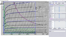
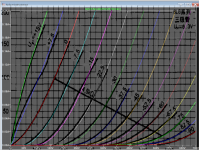
The tube current of previous ef86 was out a bit. Now I remodel using triode curve in original datasheet, it's fine.
Code:
**** EF86P ******************************************
* Created on 12/06/2018 03:41 using paint_kip.jar
* [url=http://www.dmitrynizh.com/tubeparams_image.htm]Model Paint Tools: Trace Tube Parameters over Plate Curves, Interactively[/url]
* Plate Curves image file: ef86p.png
* Data source link: <plate curves URL>
*----------------------------------------------------------------------------------
.SUBCKT EF86P P G2 G K ; LTSpice tetrode.asy pinout
* .SUBCKT EF86P P G K G2 ; Koren Pentode Pspice pinout
+ PARAMS: MU=40.33 KG1=1624.62 KP=276.8 KVB=840.17 VCT=0 EX=1.076 KG2=971.51 KNEE=5.821 KVC=1.712
+ KLAM=1.793E-13 KLAMG=2.281E-4   KNK=-0.044 KNG=0.006 KNPL=50 KNSL=11 KNPR=120 KNSR=29
+ CCG=3P CGP=1.4P CCP=1.9P RGI=2000.0
* Vp_MAX=400 Ip_MAX=8 Vg_step=1 Vg_start=0 Vg_count=21
* X_MIN=85 Y_MIN=21 X_SIZE=737 Y_SIZE=733 FSZ_X=1550 FSZ_Y=878 XYGrid=false
* Rp=1400 Vg_ac=20 P_max=1 Vg_qui=-10 Vp_qui=300
* showLoadLine=n showIp=y isDHP=n isPP=n isAsymPP=n isUL=n showDissipLimit=y
* showIg1=n isInputSnapped=y addLocalNFB=n
* XYProjections=n harmonicPlot=y dissipPlot=n
* UL=0.43 EG2=140 gridLevel2=n addKink=y isTanhKnee=n advSigmoid=n
*----------------------------------------------------------------------------------
RE1  7 0  1G    ; DUMMY SO NODE 7 HAS 2 CONNECTIONS
E1   7 0  VALUE=  ; E1 BREAKS UP LONG EQUATION FOR G1.
+{V(G2,K)/KP*LOG(1+EXP((1/MU+(VCT+V(G,K))/SQRT(KVB+V(G2,K)*V(G2,K)))*KP))}
RE2  6 0  1G    ; DUMMY SO NODE 6 HAS 2 CONNECTIONS
E2  6 0  VALUE={(PWR(V(7),EX)+PWRS(V(7),EX))} ; Kg1 times KIT current
RE21 21 0 1
E21  21 0 VALUE={V(6)/KG1*ATAN(V(P,K)/KNEE)} ; Ip with knee but no slope and no kink
RE22 22 0 1 ; E22: kink curr deviation for plate
E22  22 0 VALUE={V(21)*LIMIT(KNK-V(G,K)*KNG,0,0.3)*(-ATAN((V(P,K)-KNPL)/KNSL)+ATAN((V(P,K)-KNPR)/KNSR))}
G1   P  K  VALUE={V(21)*(1+KLAMG*V(P,K))+KLAM*V(P,K) + V(22)}
* Alexander Gurskii screen current, see audioXpress 2/2011, with slope and kink added
RE43 43 K 1G ; Dummy
E43  43 G2 VALUE={0} ; Dummy
G2   43 K  VALUE={V(6)/KG2*(KVC-ATAN(V(P,K)/KNEE))/(1+KLAMG*V(P,K))-V(22)}
RCP  P K  1G     ; FOR CONVERGENCE
C1   K G  {CCG}  ; CATHODE-GRID 1
C2   G P  {CGP}  ; GRID 1-PLATE
C3   K P  {CCP}  ; CATHODE-PLATE
R1   G 5  {RGI}  ; FOR GRID CURRENT
D3   5 K  DX     ; FOR GRID CURRENT }
.MODEL DX D(IS=1N RS=1 CJO=10PF TT=1N)
.ENDS
*$


* The following triode model is derived from pentode model, see above.
* In the triode model, all spice parameters come directly from the pentode model, except for Kg1,
* which for triode-strapped pentodes is derived from pentode's Kg1, Kg2 and Kvc as
*
*    4Kg1Kg2 / ((2Kvc-Pi)(2Kg1+PiKg2))

**** EF86P ******************************************
* Created on 12/06/2018 03:41 using paint_kit.jar 4.7
* [url=http://www.dmitrynizh.com/tubeparams_image.htm]Model Paint Tools: Trace Tube Parameters over Plate Curves, Interactively[/url]
* Plate Curves image file: ef86p.png
* Data source link: <plate curves URL>
*----------------------------------------------------------------------------------
.SUBCKT TRIODE_EF86P 1 2 3 ; Plate Grid Cathode
+ PARAMS: CCG=3P  CGP=1.4P CCP=1.9P RGI=2000
+ MU=40.33 KG1=3547.82 KP=276.8 KVB=840.17 VCT=0 EX=1.076
* Vp_MAX=400 Ip_MAX=8 Vg_step=1 Vg_start=0 Vg_count=21
* Rp=1400 Vg_ac=20 P_max=1 Vg_qui=-10 Vp_qui=300
* X_MIN=85 Y_MIN=21 X_SIZE=737 Y_SIZE=733 FSZ_X=1550 FSZ_Y=878 XYGrid=false
* showLoadLine=n showIp=y isDHT=n isPP=n isAsymPP=n showDissipLimit=y
* showIg1=n gridLevel2=n isInputSnapped=y
* XYProjections=n harmonicPlot=y dissipPlot=n
*----------------------------------------------------------------------------------
E1 7 0 VALUE={V(1,3)/KP*LOG(1+EXP(KP*(1/MU+(VCT+V(2,3))/SQRT(KVB+V(1,3)*V(1,3)))))}
RE1 7 0 1G  ; TO AVOID FLOATING NODES
G1 1 3 VALUE={(PWR(V(7),EX)+PWRS(V(7),EX))/KG1}
RCP 1 3 1G   ; TO AVOID FLOATING NODES
C1 2 3 {CCG} ; CATHODE-GRID
C2 2 1 {CGP} ; GRID=PLATE
C3 1 3 {CCP} ; CATHODE-PLATE
D3 5 3 DX ; POSITIVE GRID CURRENT
R1 2 5 {RGI} ; POSITIVE GRID CURRENT
.MODEL DX D(IS=1N RS=1 CJO=10PF TT=1N)
.ENDS
*$
Attachments
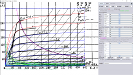
Found triode mode of 6L6 surprisingly closed to 6p3p, hence here is the remodel:
Code:
**** 6P3P ******************************************
* Created on 12/09/2018 01:26 using paint_kip.jar
* [url=http://www.dmitrynizh.com/tubeparams_image.htm]Model Paint Tools: Trace Tube Parameters over Plate Curves, Interactively[/url]
* Plate Curves image file: 6p3p.png
* Data source link: <plate curves URL>
*----------------------------------------------------------------------------------
.SUBCKT 6P3P P G2 G K ; LTSpice tetrode.asy pinout
* .SUBCKT 6P3P P G K G2 ; Koren Pentode Pspice pinout
+ PARAMS: MU=8.568 KG1=3129.28 KP=48.67 KVB=482.12 VCT=0.61 EX=1.531 KG2=6322.41 KNEE=18.32 KVC=1.676
+ KLAM=5.605E-8 KLAMG=1.532E-4   KNK=-0.044 KNG=0.006 KNPL=50 KNSL=11 KNPR=120 KNSR=29
+ CCG=11P CGP=1.5P CCP=9.5P RGI=2000.0
* Vp_MAX=440 Ip_MAX=320 Vg_step=5 Vg_start=10 Vg_count=16
* X_MIN=58 Y_MIN=74 X_SIZE=921 Y_SIZE=664 FSZ_X=1550 FSZ_Y=878 XYGrid=false
* Rp=1400 Vg_ac=20 P_max=20 Vg_qui=-27.5 Vp_qui=300
* showLoadLine=n showIp=y isDHP=n isPP=n isAsymPP=n isUL=n showDissipLimit=y
* showIg1=n isInputSnapped=y addLocalNFB=n
* XYProjections=n harmonicPlot=y dissipPlot=n
* UL=0.43 EG2=250 gridLevel2=n addKink=y isTanhKnee=n advSigmoid=n
*----------------------------------------------------------------------------------
RE1  7 0  1G    ; DUMMY SO NODE 7 HAS 2 CONNECTIONS
E1   7 0  VALUE=  ; E1 BREAKS UP LONG EQUATION FOR G1.
+{V(G2,K)/KP*LOG(1+EXP((1/MU+(VCT+V(G,K))/SQRT(KVB+V(G2,K)*V(G2,K)))*KP))}
RE2  6 0  1G    ; DUMMY SO NODE 6 HAS 2 CONNECTIONS
E2  6 0  VALUE={(PWR(V(7),EX)+PWRS(V(7),EX))} ; Kg1 times KIT current
RE21 21 0 1
E21  21 0 VALUE={V(6)/KG1*ATAN(V(P,K)/KNEE)} ; Ip with knee but no slope and no kink
RE22 22 0 1 ; E22: kink curr deviation for plate
E22  22 0 VALUE={V(21)*LIMIT(KNK-V(G,K)*KNG,0,0.3)*(-ATAN((V(P,K)-KNPL)/KNSL)+ATAN((V(P,K)-KNPR)/KNSR))}
G1   P  K  VALUE={V(21)*(1+KLAMG*V(P,K))+KLAM*V(P,K) + V(22)}
* Alexander Gurskii screen current, see audioXpress 2/2011, with slope and kink added
RE43 43 K 1G ; Dummy
E43  43 G2 VALUE={0} ; Dummy
G2   43 K  VALUE={V(6)/KG2*(KVC-ATAN(V(P,K)/KNEE))/(1+KLAMG*V(P,K))-V(22)}
RCP  P K  1G     ; FOR CONVERGENCE
C1   K G  {CCG}  ; CATHODE-GRID 1
C2   G P  {CGP}  ; GRID 1-PLATE
C3   K P  {CCP}  ; CATHODE-PLATE
R1   G 5  {RGI}  ; FOR GRID CURRENT
D3   5 K  DX     ; FOR GRID CURRENT }
.MODEL DX D(IS=1N RS=1 CJO=10PF TT=1N)
.ENDS
*$


* The following triode model is derived from pentode model, see above.
* In the triode model, all spice parameters come directly from the pentode model, except for Kg1,
* which for triode-strapped pentodes is derived from pentode's Kg1, Kg2 and Kvc as
*
*    4Kg1Kg2 / ((2Kvc-Pi)(2Kg1+PiKg2))

**** 6P3P ******************************************
* Created on 12/09/2018 01:26 using paint_kit.jar 4.7
* [url=http://www.dmitrynizh.com/tubeparams_image.htm]Model Paint Tools: Trace Tube Parameters over Plate Curves, Interactively[/url]
* Plate Curves image file: 6p3p.png
* Data source link: <plate curves URL>
*----------------------------------------------------------------------------------
.SUBCKT TRIODE_6P3P 1 2 3 ; Plate Grid Cathode
+ PARAMS: CCG=11P  CGP=1.5P CCP=9.5P RGI=2000
+ MU=8.568 KG1=14399.61 KP=48.67 KVB=482.12 VCT=0.61 EX=1.531
* Vp_MAX=440 Ip_MAX=320 Vg_step=5 Vg_start=10 Vg_count=16
* Rp=1400 Vg_ac=20 P_max=20 Vg_qui=-27.5 Vp_qui=300
* X_MIN=58 Y_MIN=74 X_SIZE=921 Y_SIZE=664 FSZ_X=1550 FSZ_Y=878 XYGrid=false
* showLoadLine=n showIp=y isDHT=n isPP=n isAsymPP=n showDissipLimit=y
* showIg1=n gridLevel2=n isInputSnapped=y
* XYProjections=n harmonicPlot=y dissipPlot=n
*----------------------------------------------------------------------------------
E1 7 0 VALUE={V(1,3)/KP*LOG(1+EXP(KP*(1/MU+(VCT+V(2,3))/SQRT(KVB+V(1,3)*V(1,3)))))}
RE1 7 0 1G  ; TO AVOID FLOATING NODES
G1 1 3 VALUE={(PWR(V(7),EX)+PWRS(V(7),EX))/KG1}
RCP 1 3 1G   ; TO AVOID FLOATING NODES
C1 2 3 {CCG} ; CATHODE-GRID
C2 2 1 {CGP} ; GRID=PLATE
C3 1 3 {CCP} ; CATHODE-PLATE
D3 5 3 DX ; POSITIVE GRID CURRENT
R1 2 5 {RGI} ; POSITIVE GRID CURRENT
.MODEL DX D(IS=1N RS=1 CJO=10PF TT=1N)
.ENDS
*$
Attachments
Last edited:
- Home
- Amplifiers
- Tubes / Valves
- Vacuum Tube SPICE Models