Dual mono quasi star point:
All incoming and outgoing mass connections meet at a focused star point (less than 1/2 cm), right at the place where the local reservoir cups are located
- signal IN
- headphone OUT
- line OUT
- voltage regulators IN
- external case transformer rectifier stage IN (external box for transformers + minimised flexi boards)
Attachments
Last edited:
The board shows thick copper to easier do your thing. Take care not to refer signal returns directly where PSU recombination ripple currents meet in your final config.
I understand your concerns and why you may have chosen mass scheme as you did, thanks for pointing me there anyway.
In case strange effects may happen with my take on star mass, it will be very easy to go one step back. Variants have had worked for me at many occasions, always proven to increase perceived resolution, so I'm confident this may not become necessary.
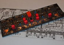
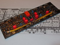
Board quality is gorgeous. 🙂
In case strange effects may happen with my take on star mass, it will be very easy to go one step back. Variants have had worked for me at many occasions, always proven to increase perceived resolution, so I'm confident this may not become necessary.
Board quality is gorgeous. 🙂
Last edited:
Input impedance seen by J1 highly depends on the wiper position of the volume pot.
What could be estimated to be the sweet spot, given the recommendation for a 20k pot?
Asking, because I possibly want to omit volume control completely at one point. What value to chose for R1 by then?
What could be estimated to be the sweet spot, given the recommendation for a 20k pot?
Asking, because I possibly want to omit volume control completely at one point. What value to chose for R1 by then?
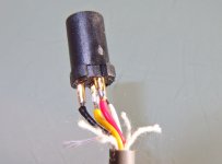
In one of the early pictures C1 seems to be a MICA type.
Salas DCG3 preamp (line & headphone)
Any effect on sound reported?
I've seen polystyrene at such places too, but usually not ceramic.
Salas DCG3 preamp (line & headphone)
Any effect on sound reported?
I've seen polystyrene at such places too, but usually not ceramic.
Last edited:
I had only used silvered mica for C1 and C2 in my prototype because I had some. So I can't comment on substitution subtleties. But C0G (NP0) had also worked flawlessly in others. Its one of the most stable capacitor dielectrics available.
Thanks, my concern with older ceramic is that they were reportedly prone to act as resonators. Not the case here as it seems.
Found another posting way back on the topic:
Salas DCG3 preamp (line & headphone)
Will try silver MICA to get a feeling regarding sound on that instance.
Found another posting way back on the topic:
Salas DCG3 preamp (line & headphone)
Will try silver MICA to get a feeling regarding sound on that instance.
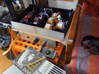
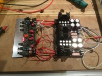
time for a first check, break in and figuring out best grounding scheme
🙂
For now anything is complete stock of the very first version two years ago, besides quasi star mass on the amp board as already shown
🙂
For now anything is complete stock of the very first version two years ago, besides quasi star mass on the amp board as already shown
Attachments
Thanks, my concern with older ceramic is that they were reportedly prone to act as resonators. Not the case here as it seems.
"Note that there are no measurable piezoelectric effects in Class 1 capacitors, such as C0G or NP0 - neither of which is considered ferroelectric." John D. Prymak – KEMET Applications Manager
PIEZOELECTRIC EFFECTS (Singing Capacitors)
Salas, at this point I'd like to say a big thank you for that capable design of yours!
Also I'd like to say a big thank you to Tea-Bag for all the effort he puts into making it available as GB!
So much work to match all those components, it worked out very well right from the start, with no hassles at all. Was like playing LEGO.
After systematic grounding, the amp is dead quiet and the initially unbearable piano sound has smoothed out completely. Still slightly veiled sound at this early time of break in.
I'm eagerly awaiting a 100pc batch of BC237-40 to replace original Q1 Q2 BC560C, and after that my first mod until UltraBiB will arrive, I'll try RC decoupling of the first stage.
This should be indicative as the DCSTB PS is weaker, so there is even less interstage decoupling than with the low Z UBiB
Fun time to come, that's for sure. 🙂
You're welcome. Little patience and some planned substitutions along more play time will surely lead you to most favorite and synergistic configuration for amping your modded AKG K712 cans. Keep us posted.
Help, high DC offset
Hi All,
Just doing initial testing on my DCG3 and I have what I think is very high DC offset. May I have some advice on how to proceed? I don't want to destroy anything.
A little background:
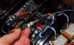
DCSTB is showing 17.06 to 17.12 VDC on both sides.
DCG3 lit up very nicely after a brief delay (perhaps 4 or 5 seconds), no smoke or strange noises. I let it cook for 15 minutes. The little heat sink (which will ultimately be bolted to the chassis bottom plate) measured about 45C in the middle and about 51C closer to the ends.
R10 is 6R8 and with 1.06 to 1.12V suggests bias of about 155mA to 160mA bias (57 ohm headphones).
I shorted the signal inputs (granted the alligator clips are lousy, but I am getting continuity between the pads) and measured DC offset of 545mA. This is nearly identical between channels. Twiddling VR1 gets me no lower than 530mA. I can't get anywhere close to the few mV around zero offset indicated in step 7 of the build guide.
So, I think I must have made some mistake. May I please have some guidance as to the most likely places to look for misplaced parts, wrong values, etc?
Thanks!
Hi All,
Just doing initial testing on my DCG3 and I have what I think is very high DC offset. May I have some advice on how to proceed? I don't want to destroy anything.
A little background:
DCSTB is showing 17.06 to 17.12 VDC on both sides.
DCG3 lit up very nicely after a brief delay (perhaps 4 or 5 seconds), no smoke or strange noises. I let it cook for 15 minutes. The little heat sink (which will ultimately be bolted to the chassis bottom plate) measured about 45C in the middle and about 51C closer to the ends.
R10 is 6R8 and with 1.06 to 1.12V suggests bias of about 155mA to 160mA bias (57 ohm headphones).
I shorted the signal inputs (granted the alligator clips are lousy, but I am getting continuity between the pads) and measured DC offset of 545mA. This is nearly identical between channels. Twiddling VR1 gets me no lower than 530mA. I can't get anywhere close to the few mV around zero offset indicated in step 7 of the build guide.
So, I think I must have made some mistake. May I please have some guidance as to the most likely places to look for misplaced parts, wrong values, etc?
Thanks!
Attachments

If I remember correctly, Q1 and Q2 came as matched pairs.
If you can't adjust below this half volt offset on both channels, it might be you mixed them.
If that's been the case, you could try to unsolder one of the right and one of the left channel and switch places.
Can you possibly check by signal generator and oscilloscope (or even AC multimeter) if basic operation works well besides the offset?
Last edited:
Basic things like the right MOSFET types order or the electrolytics orientations look correct. Check the insulation of each MOSFET's tab to the metal bar sink with the DMM's continuity beeper first. It must not beep. In case it beeps fix the insulation on the one it did. If no fault there, then measure some voltages: See that Q1 and Q2 show about 0.6V Vbe each (dc voltage between base and emitter). The drop in mV across R3 must indicate about 5mA when divided by its Ohms. Vgs (dc voltage across first and last leg) for M1 & M2 about 4V but lower for M3, about 1-2V. Voltage between M1's drain (middle leg) and ground must read at almost half the positive supply voltage.
- Home
- Source & Line
- Analog Line Level
- Salas DCG3 preamp (line & headphone)