I just finished this little amp.
One heads up I will give, the red OPT wire does not go the the B+. You have to wire it "backwards" for the negative feedback to be negative.
When I was finished, I had a few left over parts. I had found a different diagram on line and built from it. It didn't include a bypass cap with the drivers cathode biasing resister, so I assume my build will have a little less gain, but it has enough.
Another 2 errors I made, I forgot to include a wire from RCAs to ground, so I had a big hum box, and I wired the pot backwards, so volume doesn't work right.
The power transformer runs a little hotter than I would like. By my Pass finger thermometer, I would guess around 160 degF.
I've ran it about 12 hrs so far with just a cheap set of pioneer bookshelf speakers and a 90s sony CD player, but I think it's a decent little amp. It doesn't fall on it's face in a pile of p1ss and blood after a minor overdrive.
Man up and finish it or leave this hobby forever. (Joking, but yes, it is worth finishing unless you have better uses for it's components.) The stainless chassis and enclosed trannies are actually quite attractive.
I have a gemtune x1 which is the el34 version of this in an Imho better looking chassis. I also paid closer to 300 for it so you are way ahead in the budget department. Se pentode isn't everyone's cup of tea but i like this amp running my emilar horns and it sounded surprising good with some more conventional speakers too. Persevere it will be worth it I promise.
Why not post photos of what you have so far and folks can give you pointers?
Where are you located? There also might be someone local willing to spend a Saturday getting it finished off if you keep them we'll fed and hydrated.
Why not post photos of what you have so far and folks can give you pointers?
Where are you located? There also might be someone local willing to spend a Saturday getting it finished off if you keep them we'll fed and hydrated.
Last edited:
I've considered picking up one of these kits, the iron, chassis, and accessories (I/O jacks, etc) make it worth the price, and it looks like a versatile little setup to play with for sure. May be a fun starting point for a 6AV5 SE Triode build with a different driver tube 🙂
and I wired the pot backwards, so volume doesn't work right.
Yes, as I mentioned before, the pot had to be soldered at opposite side, standing on traces.
The power transformer runs a little hotter than I would like. By my Pass finger thermometer, I would guess around 160 degF.
Insulate bolts, as I mentioned before, and the transformer will be decent.
I've considered picking up one of these kits, the iron, chassis, and accessories (I/O jacks, etc) make it worth the price, and it looks like a versatile little setup to play with for sure. May be a fun starting point for a 6AV5 SE Triode build with a different driver tube 🙂
It worth it for the chassis and iron. I planned to build one improved version of Edelweiss, looking for some cheap ready to use chassis, when found this kit. However, to drill it I had to use high speed drill bit with coolant, but Greenlee punch works well to increase diameters of existing holes.
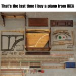
However, this kit reminds me what is on the picture that I attached: if you don't know how to build you would not be able to build it. But if you know how to build you would not want to build it as is. However, with proper guidance, you can build it, and get an experience and some understanding.
Attachments
Insulate bolts, as I mentioned before, and the transformer will be decent.
Newbie here: could you please quick explain why insulating bolts will lower heat and/or make decent? Seeking to understand.
Thanks!
Last edited by a moderator:
Newbie here: could you please quick explain why insulating bolts will lower heat and/or make decent? Seeking to understand.
Go back and read post #13, 1....
jeff
I purchased one of those cheap Chinese tube amp kits....
I have very little knowledge about circuits and what the various parts do....
The endless research done to figure out were to start led me here where I found out ....
B. It is a poorly designed amp.
My question is what should I do next? (It is a multiple-choice question)
..
B. Finish it, plug it in, turn it on and take out the power grid for miles then throw it away and tell myself it was only $140
...
D. Stop now take it to a tech and let them finish it. Making this a $300+ poorly designed amp...
Your multiple choice section of post#1 exudes frustration imho - and many here can empathize with you as we all have had a learning curve of some form.
Your comment about 'poorly designed amp' was a bit rich imho. It sounded like you were stereotyping cheap kit amps, without any experience. Perhaps you really meant that the kit was poorly documented for diy construction and testing/fault finding and non-country-of-origin. Again, a topic many of us can empathize with even for very well known, professional and expensive equipment in a variety of fields.
Newbie here: could you please quick explain why insulating bolts will lower heat and/or make decent? Seeking to understand.
Lots of good info here:
Earthing (Grounding) Your Hi-Fi - Tricks and Techniques
and here:
http://www.valvewizard.co.uk/Grounding.pdf
Go back and read post #13, 1....
jeff
yeah, had read those, that further explains nothing. I get the ground loop issues (thanks other poster) and maybe bolt insulation helping any mechanical vibration against the chassis, but why would it run "less hotter" by doing that?
I can see added holes for venting, but doesn't explain why running hot to begin with. 110V primary on 120V? Poor design?
Thanks! Great content.
Found this among many other insights: "Should the transformer be of 'conventional' construction (not a toroidal), then the transformer body - the steel core - must be connected to chassis directly. Do not use any loop breaker circuit to isolate the transformer core, as it is unnecessary and dangerous to do so."
Newbie here: could you please quick explain why insulating bolts will lower heat and/or make decent? Seeking to understand.
Bolts form a turn around magnetic field that is shorted. Magnetic field causes in this turn a voltage, loaded on it's DC resistance. Electromagnetic energy gets turned into heat.
I had to noodle on it a while as the bolts are not in the winding window, I questioned the shorted turn theory. The bolts are NOT outside the laminations. They are half way through the flux field in the laminations, so they do make sort of a 1/2 shorted turn (but 2 of them).
Another solution would be lop the corners off of the transformer core, but that would likely saturate the iron at the truncated corners, and be difficult to do neatly.
I need to make a trek to the local electronic surplus store to get some insulating fiber washers. I think the easier way to insulate will be heat shrink the shank of the screws (hoping it still fits the hole) and using a fiber washer on the top cover for all but one bolt. I'll leave one uninsulated to ground the cover bell.
I can see added holes for venting, but doesn't explain why running hot to begin with. 110V primary on 120V? Poor design?
110/50 Hz, it is fine
E. None of the above.
If you had your basic location, there may be others near you willing to help.
You could build it and post pics of your progress and seek advice during the build process.
You could sell the kit if you can't get it to work, as not working.
If you had your basic location, there may be others near you willing to help.
You could build it and post pics of your progress and seek advice during the build process.
You could sell the kit if you can't get it to work, as not working.
o110/50 Hz, it is fine
You, DonQ and I should all be in the 60Hz world, but if it works at 110V 50hz, it'll be fine at up to 120V 60hz... unless the governor spring on your generator is getting saggy.
Some tips.
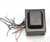
1. You have to insulate bolts in the transformer to remove the shorted turn that they cause. Remove them, add plastic T-nuts, and heatshrink tubing on them, then put them back.
I don't understand how this power transformer is different than all the other (laydown) power transformers I've seen over the years, and they were all fastened with steel bolts, to the chassis.
Can somebody please explain what I'm missing? I know the idea of a shorted turn when using toroidal transformers, but I don't see how this transformer is similar.
Thanks!
Attachments
Different kit, but still deja-vu for me...
Building something better with a Chinese SE EL34B Amp DIY Kit
🙂
BTW, that amp seems to have a similar PT.... should I go back and fasten the transformer with nylon connectors?
Building something better with a Chinese SE EL34B Amp DIY Kit
🙂
BTW, that amp seems to have a similar PT.... should I go back and fasten the transformer with nylon connectors?
What they're saying is that the bolts that hold it together need to be insulated from the lamination, to reduce eddy currents, which could cause a heat buildupI don't understand how this power transformer is different than all the other (laydown) power transformers I've seen over the years, and they were all fastened with steel bolts, to the chassis.
Can somebody please explain what I'm missing? I know the idea of a shorted turn when using toroidal transformers, but I don't see how this transformer is similar.
Thanks!
This is something that Scott, Fisher, Heathkit, etc all missed?What they're saying is that the bolts that hold it together need to be insulated from the lamination, to reduce eddy currents, which could cause a heat buildup
I'm still scratching my head on this.
- Status
- Not open for further replies.
- Home
- Amplifiers
- Tubes / Valves
- Another Newbie Who Bought a Cheap Chinese Tube Amp Kit