Hornresp Update 4850-181121
Hi Everyone,
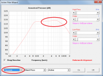
The filter wizard now works with both pressure and power responses. My thanks to papasteack for highlighting the limitation introduced with the release of Version 42.10.
Kind regards,
David
Hi Everyone,
The filter wizard now works with both pressure and power responses. My thanks to papasteack for highlighting the limitation introduced with the release of Version 42.10.
Kind regards,
David
Attachments

Thanks! I`ll give the pressure screen a try. The horn data in your link is for a horn with a much larger mouth?That's gonna be quite the stack, if you have close to corner placement you probably are close to 1 x pi.
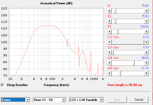
Your horn is a bit on the peaky side, if you go to the pressure screen and [ctrl]+[x] you can poke around a bit and see the built-in gain on and off axis, this is much easier to see in 2 x pi.
Then try your driver in this. It's not specific to your driver but plug the 2220H in and give it a go. You can squeeze the rear chamber down to 20l to push up the bottom end a bit. This horn is a bit of a cheat in that it is intentionally made with less directivity so as not to have big swings in gain as you move off axis.
Would reflections caused by a too small mouth (contour not "full") be visible in the simulations? I think the differences in the plots are small. My Le Cleach example seems to have rather smooth response in the simulation.
That's gonna be quite the stack.
Something like this i guess:
Attachments

Hi Everyone,
The filter wizard now works with both pressure and power responses. My thanks to papasteack for highlighting the limitation introduced with the release of Version 42.10.
Kind regards,
David
Thanks a lot ! Just played with it. Filter set on a 0° directivity can be kept ON and so we can lauch a directivity polar pattern taking account of filter setting. Magical. So i can now try to correct my built error so easier, more confident.
And i just came to a very satisfaying variation arround 6th parrallel band pass feeding a little segment simmed as TH thanks to hornresp, with really good bandpass effect. Group delay, excursion, size, bandwith, particule velocity...everything seems really good compromise. It need Qes 0,23, light mss 12" sub (around 85gr), so small long voicecoil. Will have to custom one

Attachments
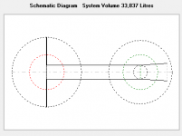
Now that looks like a great stack for my living room. Lol.Something like this i guess:
Question.
Sealed boxes are reccomended to have 1lb/cu fut polyfill. In hornresp what are the input setting for that amount of stuffing?
Sealed boxes are reccomended to have 1lb/cu fut polyfill. In hornresp what are the input setting for that amount of stuffing?
A PolyFill density of 1 pound per cubic foot is approximately equal to an absorbent material airflow resistivity (Fr) of 870 mks rayls/m.
schematics of speaker boxes in Hornresp manual
Dear David ,
Thanks for your kind email response and here are a couple of suggestions that would make using HORNRESP at lot easier for us ,or me.
- having drawings of cross sectional speaker boxes of different sorts ie..transmission lines,scoops etc. with named abbreviations relating to software input fields.
-how can we model transmission lines with sealed or vented Front chambers.
Thank you so much for putting the effort into this amazing program.
I already used it to build one of the most beautiful subs ever.
Hm.. I can`t say I find this pressure screen..That's gonna be quite the stack, if you have close to corner placement you probably are close to 1 x pi.
Your horn is a bit on the peaky side, if you go to the pressure screen and [ctrl]+[x] you can poke around a bit and see the built-in gain on and off axis, this is much easier to see in 2 x pi.
Should a throat adapter be used with the example Le Cleach further up? I tried to use the throat adaptor designer, but I`m not sure what the D1 and D2 is? Is D2 the same as the diameter of the driver ( Atc)? Is the D1 the same as the width/height at S1 (Ap1)? Is the driver front volume the same as Vtc? what would the throat adaptor look like?
Thanks🙂 At least I know what the parameters are. I`ll try to visualize what the adapter will look like..
Hi mgabr,
Not a problem 🙂.
The reason that cross-sectional drawings are not provided is primarily because there are just so many different loudspeaker designs to choose from. I have attempted to include band pass enclosure drawings, which are relatively simple, but even then, problems have arisen in how they should be interpreted.
The Input Wizard tool, accessed from the Help menu, can always be used if you are not sure which input parameters apply to a particular design.
I am not certain that I understand what you mean by a transmission line with a sealed or vented front chamber. Can you provide further details, please?
(Questions relating specifically to Hornresp can be posted to the main Hornresp thread, which keeps everything in the same place, and helps to avoid the proliferation of multiple small threads on the same general subject).
Kind regards,
David
Thanks for your kind email response
Not a problem 🙂.
- having drawings of cross sectional speaker boxes of different sorts ie..transmission lines,scoops etc. with named abbreviations relating to software input fields.
The reason that cross-sectional drawings are not provided is primarily because there are just so many different loudspeaker designs to choose from. I have attempted to include band pass enclosure drawings, which are relatively simple, but even then, problems have arisen in how they should be interpreted.
The Input Wizard tool, accessed from the Help menu, can always be used if you are not sure which input parameters apply to a particular design.
how can we model transmission lines with sealed or vented Front chambers.
I am not certain that I understand what you mean by a transmission line with a sealed or vented front chamber. Can you provide further details, please?
(Questions relating specifically to Hornresp can be posted to the main Hornresp thread, which keeps everything in the same place, and helps to avoid the proliferation of multiple small threads on the same general subject).
Kind regards,
David
Attachments

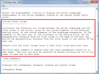
Yes, my questions were perhaps not crystal clear.. But I still have to find out if a throat adapter is needed? If so, I got confused by the numbers D1, D2 and the angles that are already there when I opened the Throat Adaptor Designer. And they doesn`t change when inputing numbers in Ap1 and Lp in the Input Parameters screen.Your questions relate the Throat Adaptor Designer tool.
Dan's response applies to the Driver Front Volume tool.
It seems that the two of you may be talking at cross-purposes...
Attachments
Oops, my bad, in this sort of construction I guess the board in front of the baffle could be considered as a throat adapter if it has no expansion angle.
OK. I have seen some examples of throat chambers on horns with cone drivers, but I don`t know when it is required or recommended..Oops, my bad, in this sort of construction I guess the board in front of the baffle could be considered as a throat adapter if it has no expansion angle.
OK. I have seen some examples of throat chambers on horns with cone drivers, but I don`t know when it is required or recommended..
It's probably not going to be beneficial to add an extra volume to the interface between the driver and horn.
I have observed that when you get into the midrange and higher up there are many creative attempts at minimizing the volume between the driver and horn with phase plugs and similar devices as you typically see built into compression drivers.
Yes, my questions were perhaps not crystal clear.. But I still have to find out if a throat adapter is needed? If so, I got confused by the numbers D1, D2 and the angles that are already there when I opened the Throat Adaptor Designer. And they doesn`t change when inputing numbers in Ap1 and Lp in the Input Parameters screen.
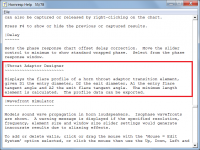
The Throat Adaptor Designer is a stand-alone tool, it does not interact in any way with the Input Parameters window. The default values shown when the tool is opened are just indicative values to generate a representative result. The tool is normally used when designing an axisymmetric (circular cross-section) transition piece to match a given compression driver to a given horn.
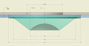
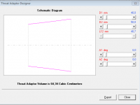
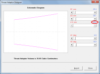
For example, to match a compression driver with an outlet diameter of 1 inch and an outlet half-angle of 6 degrees, to a horn with a throat diameter of 1.5 inches and a throat flare tangent angle of 10 degrees:
D1 = 25.4 mm (1" transition entry diameter)
A1 = 6 degrees (transition entry flare tangent angle)
D2 = 38.1 mm (1.5" transition exit diameter)
A2 = 10 degrees (transition exit flare tangent angle)
The resulting transition piece will have an axial length of 45.2 mm, as shown in Attachment 1. The exported dimensional data required to make the transition piece, is given in Attachment 2.
Attachments
- Home
- Loudspeakers
- Subwoofers
- Hornresp