I'd suspect that only the RC-product/timeconstant is important. So to lower the capacitance, increase the resistor.
That doesn't seem to work:
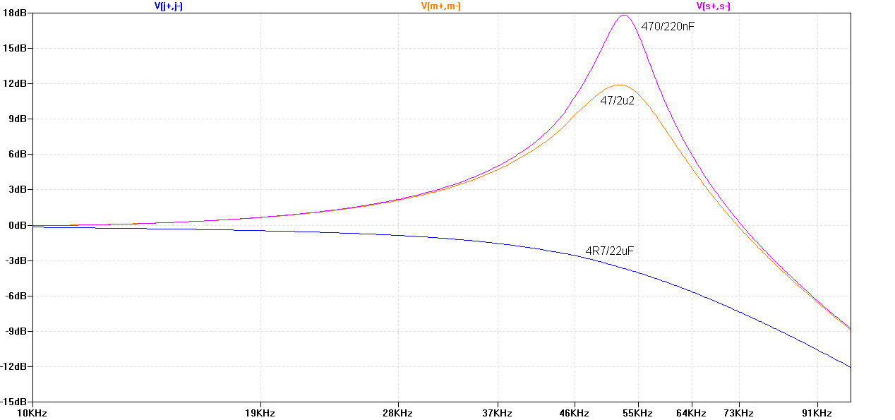
A highish resistance of 470 Ohms is like an open circuit (i.e. it doesn't have any effect), regardless of the capacitor used.
The low resistance value seems to be important. This is what happens when I leave it at 4R7 and only change the capacitor:
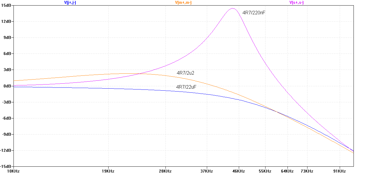
There must be something more to it than the time constant (which is around 1.5kHz for 4R7/22uF 😕)
These plots were all done with the S6 speaker model, don't let the labels mislead you.
A highish resistance of 470 Ohms is like an open circuit (i.e. it doesn't have any effect), regardless of the capacitor used.
The low resistance value seems to be important. This is what happens when I leave it at 4R7 and only change the capacitor:
There must be something more to it than the time constant (which is around 1.5kHz for 4R7/22uF 😕)
These plots were all done with the S6 speaker model, don't let the labels mislead you.
Attachments

You're welcome 🙂.
I'll try such a zobel once I have the boards and see how they affect the THD readings (and probably passband ripple) with a real speaker connected.
I'll try such a zobel once I have the boards and see how they affect the THD readings (and probably passband ripple) with a real speaker connected.
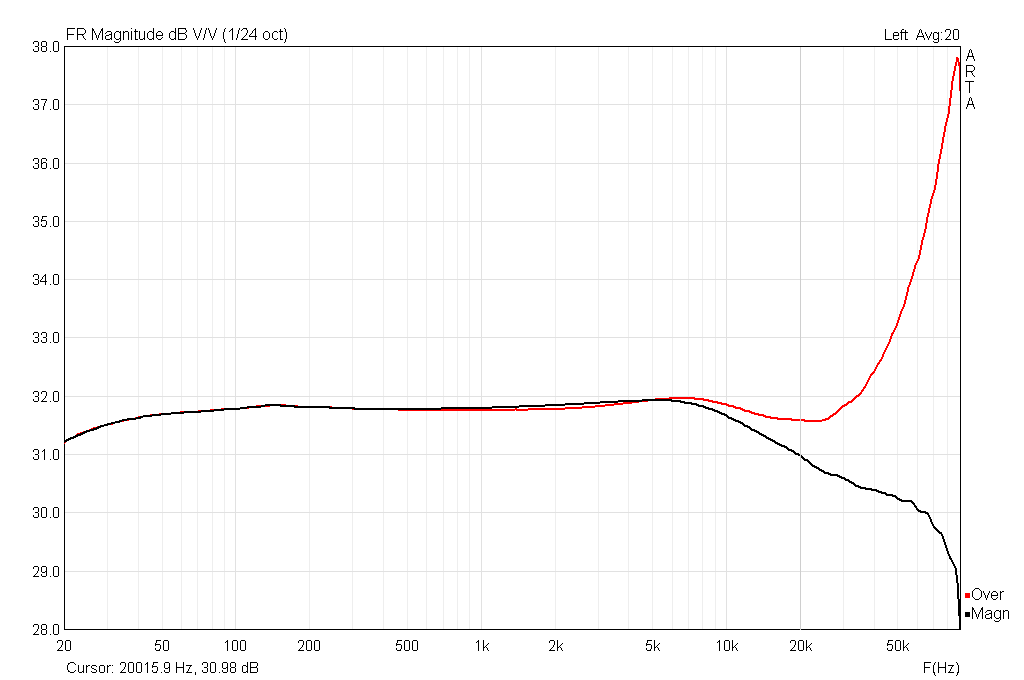
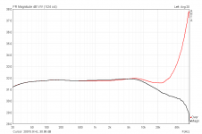
Here's a first frequency response test with a blue "Sanwa" TPA3118 board, powered by a 19V laptop brick. The JVC speaker and model were used for this test.
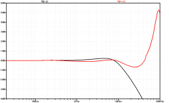
I probably cheated a bit here, but maybe not. The simulation was done with 10uH and 400nF on the output filter, to achieve a peak around 90kHz, like in the real-world measurement. The actual ceramic filter capacitor measures more like 800nF in-circuit, but due to it being ceramic, it might have less capacitance with the output voltage applied. Apart from that, the graphs line up pretty well I think.
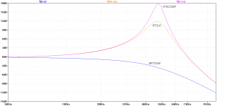
Red trace is speaker-only, black trace is with an added Zobel comprised of 4R7 and two anti-serial 47uF electrolytics.

I'll make some THD measurements soon.
I probably cheated a bit here, but maybe not. The simulation was done with 10uH and 400nF on the output filter, to achieve a peak around 90kHz, like in the real-world measurement. The actual ceramic filter capacitor measures more like 800nF in-circuit, but due to it being ceramic, it might have less capacitance with the output voltage applied. Apart from that, the graphs line up pretty well I think.
Red trace is speaker-only, black trace is with an added Zobel comprised of 4R7 and two anti-serial 47uF electrolytics.
I'll make some THD measurements soon.
Attachments
Now check power dissipation inside zobel res and you will find it burning with 47uf zobel cap at frequencies of several khz with higher output levels.
zobel cap should not exceed 3xfilter cap, 47uf are an absolute no go.
a ltspice power loss simulation will confirm this.
zobel cap should not exceed 3xfilter cap, 47uf are an absolute no go.
a ltspice power loss simulation will confirm this.
It's ''only'' 23.5uF in this case and there's not too much HF there, as the output filter takes care of that. I will leave the zobel in and test its performance under controlled conditions when I find the time.
THD seems to be mostly unaffected. Above 5kHz it starts to increase a little less steep with the zobel (gray trace).
a ltspice power loss simulation will confirm this.
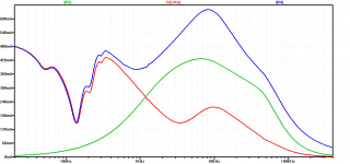
Sure, there's some current going through the zobel resistor, but how much high frequency energy is there in actual music? The switching frequency is of no concern, and a quick test (about two minutes) with a 7kHz sine wave at ear splitting volumes (1.5VRMS at the speaker) just barely got that resistor warmed up slightly. The resistor won't burn up from an idling amp and it probably won't burst in flames during normal listening.
Blue = total current
Red = speaker current
Green = zobel current
Attachments

depends and what you call normal listening. for instance one microphone feedback at 5khz in a live situation, and your resistor is magic smoke.
All in all this configuration exhibits a power bandwidth limited far below 20khz. if that is acceptable for you i am fine.
All in all this configuration exhibits a power bandwidth limited far below 20khz. if that is acceptable for you i am fine.
Last edited:
Hmm, 0.02% THD, the board can do better with better inductors like Codaca CSD0910B.
Reference:
https://e2e.ti.com/cfs-file/__key/c...Flipper_5F00_TPA3128_5F00_Codaca_5F00_5RO.png
Source:
[Resolved] TPA3128D2: THD Performance in Hybrid/1SPW vs. BD modulation when using single-ended input (compared to fully differential drive) - Audio forum - Audio - TI E2E Community
Reference:
https://e2e.ti.com/cfs-file/__key/c...Flipper_5F00_TPA3128_5F00_Codaca_5F00_5RO.png
Source:
[Resolved] TPA3128D2: THD Performance in Hybrid/1SPW vs. BD modulation when using single-ended input (compared to fully differential drive) - Audio forum - Audio - TI E2E Community
Hmm, 0.02% THD, the board can do better with better inductors like Codaca CSD0910B.
Reference:
https://e2e.ti.com/cfs-file/__key/c...Flipper_5F00_TPA3128_5F00_Codaca_5F00_5RO.png
Source:
[Resolved] TPA3128D2: THD Performance in Hybrid/1SPW vs. BD modulation when using single-ended input (compared to fully differential drive) - Audio forum - Audio - TI E2E Community
There are more things that can be improved😀
All in all this configuration exhibits a power bandwidth limited far below 20khz. if that is acceptable for you i am fine.
No mic's here, just music 😀.
I guess I can live with that for some background music in my kitchen. I'll compare the stock version with the zobeled one, to see whether it really makes an audible difference. Probably won't use those small amps for my main speakers, though.
Hmm, 0.02% THD, the board can do better with better inductors like Codaca CSD0910B.
I'll re-test the boards with Sagami DBE1010HB.
This may work under normal conditions. On the other hand this may work without the zobel as well. All in all this is a general weakness of pure prefilter feedback.No mic's here, just music 😀.
I guess I can live with that for some background music in my kitchen. I'll compare the stock version with the zobeled one, to see whether it really makes an audible difference. Probably won't use those small amps for my main speakers, though.
Last edited:
The THD actually got worse after my modifications 😱. It's more like 0.07% now (blue trace) instead of 0.02% like before. Reducing the gain to the minimum of 20dB helped to counter this, but with a slight penalty above 1kHz still remaining (green trace).
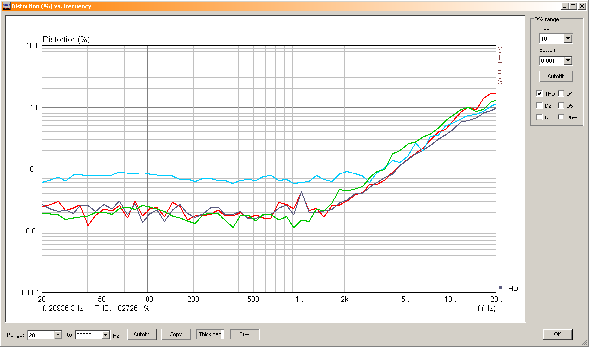
I'm not sure what exactly causes this, but it's probably the output capacitors. For one they're now actually 1uF and not changing capacitance with voltage like the ceramics did, but being polyester types they surely have a somewhat higher ESR. Does that make any difference? 😕
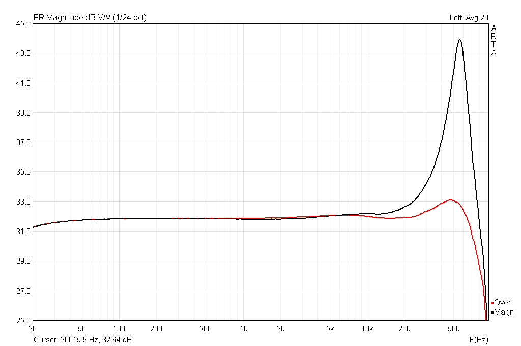
That's where the peak is supposed to show with 1uF caps: closer to 60kHz than 90kHz (colors swapped this time; peak without the zobel).
I'm not sure what exactly causes this, but it's probably the output capacitors. For one they're now actually 1uF and not changing capacitance with voltage like the ceramics did, but being polyester types they surely have a somewhat higher ESR. Does that make any difference? 😕
That's where the peak is supposed to show with 1uF caps: closer to 60kHz than 90kHz (colors swapped this time; peak without the zobel).
Attachments


- Status
- Not open for further replies.
- Home
- Amplifiers
- Class D
- Some rambling calculation on TPA3116/8 filters.