thanks for confirming. those are different designs however.Red boards that i received Today are excellent!
Thanks Prasi!😉
Hi Prasi,
Do you thing you could add the rectifier section of Project16/Prasi CRC PSU to this cap MX? I much prefer discrete diodes than square bridges.
All the best!
Do
Do you thing you could add the rectifier section of Project16/Prasi CRC PSU to this cap MX? I much prefer discrete diodes than square bridges.
All the best!
Do
Hello Pinnocchio, A design of diode section just like crc supply with SK104/129 heatsinks, etc would require a complete rework of the layout and would make the length > 100mm.
My boards have almost finished production from JLCPCB. Thanks for the gerbers Prasi! There was some discussion in another thread about slowing the ramp up of the CapMx via a revision to the RC time constant. Is there a simple way to accomplish this changing a few values? It would be a huge benefit to my ALPHA 20W build.
Hello all
Maybe a pcb with only the recovery part (to220 diodes, heatsinks and connectors) could come into being, so the choice with this pcb or bridge rectifiers standard would be possible.
Maybe a pcb with only the recovery part (to220 diodes, heatsinks and connectors) could come into being, so the choice with this pcb or bridge rectifiers standard would be possible.
Hello all
Maybe a pcb with only the recovery part (to220 diodes, heatsinks and connectors) could come into being, so the choice with this pcb or bridge rectifiers standard would be possible.
+1
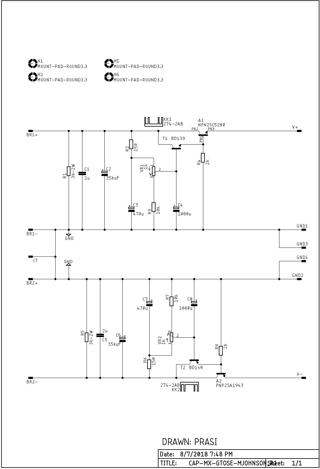
Hi Mark Johnson,
Thank you for the excellent cap mx design that you have given us. I really like how well it works. If we wanted it to have a very slow rising ramp output voltage, can we simply change R2 and R6 to adjust the R2/C3 R6/C7 RC time constant? On the Juma Easy Peasy cap mx, we have 10k and 220uF for a 0.7RC time constant of about 1.5s. This is nice for amps that have turn on thump problems as the slow rise eliminates this issue.
Can we simply change the 150R to 4k7 to really slow down the initial chargup - will it still allow the cap mx to work properly?
Thanks,
X
My "contribution" was merely to suggest three little tweaks
(a) Use a cascade of two emitter followers, so the base current drawn from the capacitor node is small, so you can use a bigger filter resistor ("R2" in post #607) and a smaller filter capacitor ("C4") yet get plenty of low frequency attenuation
(b) Connect a multiturn trimpot that lets you dial the dropout voltage (Vin - Vout) to be as large or as small as you like. It gives you a safety margin against propagating input ripple through the circuit onto the output, and you can set that safety margin as big or as small as you please.
(c) Connect the emitter resistor ("R4") of the upstream transistor ("T1") to ground, not to the output node. This reduces output impedance and improves performance with load current waveforms that are large dynamic range square waves, such as 5% to 99% to 5% to 99% to 5% etc
Other than that, the circuit belongs to whoever implements it. It's yours, it's not mine. Do with it as you like. Build it. Measure it. Simulate its behavior. If your simulation results show unexpected or weird behavior, rejoice! It's a learning experience! Dig in and understand what's going on and why things happen the way the simulator says they do. If you've made an honest and thorough effort, yet still can't understand your results, if you post your results along with your misgivings, diyAudio members could maybe offer their advice and analysis. Who knows, I might too.
Attachments
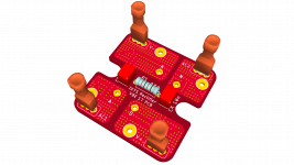
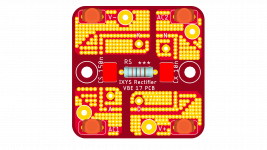
Talking of rectification, here is another one i had designed to use chassis mount type rectifiers for a customer. posted here with kind permission.
the rectifier is https://www.mouser.com/datasheet/2/205/l359-1110470.pdf
the rectifier is https://www.mouser.com/datasheet/2/205/l359-1110470.pdf
Attachments
Last edited:
😀 with new and improved features!
Hi Prasi,
I would definitely try a set of cap mx PCBs and a set of those Bridge rectifiers PCBs if you run a batch.
Thanks
Do
Prasi also made a very nice small version for headphone amps and preamps using SMT and TO220 with built in bridge. So just connect your favorite dual secondary toroidal trafo. A 25w 18v would be perfect for many preamps or headphone amps. If one wanted to, follow this with a TPS7AXXXX LDO for very low noise (4uV rms on positive rail and 16uV rms On negative rail).
Last edited:
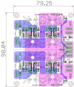
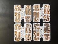
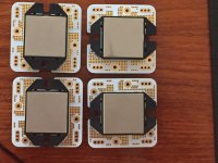
I can vouch for JLCPCB to provide a great product at a great price. Just received my CapMx boards and they are beautiful! I ordered them last Thursday, so a pretty impressive turn around considering shipping from China as well. I went with 1.6mm, 1oz boards to keep cost down since this was sort of a trial run for me. I did spring for the blue mask and ENIG finish to match most of my other project PCB's though. 😉
I sent the gerbers that Prasi re-posted on post #597. Even thought the drill file didn't display correctly on their viewer the production went perfectly. Thanks again to Prasi, gtose, Mark Johnson and everyone else for all of their contributions. Time to order some parts!
I sent the gerbers that Prasi re-posted on post #597. Even thought the drill file didn't display correctly on their viewer the production went perfectly. Thanks again to Prasi, gtose, Mark Johnson and everyone else for all of their contributions. Time to order some parts!
Attachments

Last edited:
When ordering your parts consider the following suggested by X;
Replace R2, R6 from 150 ohm to 4700 ohm, this will introduce a slower initial charging ramp.
Juma did this on his Cap Mx., he has the same RC time constant ratio.
Replace R2, R6 from 150 ohm to 4700 ohm, this will introduce a slower initial charging ramp.
Juma did this on his Cap Mx., he has the same RC time constant ratio.
Last edited:
I haven’t actually tried this yet so not sure if it is going to work as this is a BJT based circuit and it needs a certain current drive to the base of the transistor to work. The Juma cap Mx is MOSFET based so gate drive doesn’t require current.
It might be a trade off between voltage drop and time constant. One way to do it is adjust the pot to increase chargeup delay until turn on pop is not a problem. Then check the voltage. I think all that is needed is 0.5sec to avoid thump.
It might be a trade off between voltage drop and time constant. One way to do it is adjust the pot to increase chargeup delay until turn on pop is not a problem. Then check the voltage. I think all that is needed is 0.5sec to avoid thump.
When ordering your parts consider the following suggested by X;
Replace R2, R6 from 150 ohm to 4700 ohm, this will introduce a slower initial charging ramp.
Juma did this on his Cap Mx., he has the same RC time constant ratio.
R2, VR1 and the 10K resistor to ground form a voltage divider to establish the DC base voltage at the driver transistor. Even if you disregard the voltage drop due to base current, and you shouldn't, you will find the output at about 14 volts for a 25 volt input. No ripple but way too large voltage drop.
Are the Gerber files of the low power version of cap multiplier board available? I mean the ones of the board published by XRK971 in the post #613.
I'd love to make use of such compact, and surely effective, design in one of my future pre-amp.
Guys, you are doing a great job and contribution to the DIY community ... many thanks!!!
I'd love to make use of such compact, and surely effective, design in one of my future pre-amp.
Guys, you are doing a great job and contribution to the DIY community ... many thanks!!!
- Home
- Amplifiers
- Power Supplies
- Juma's Easy-Peasy Capacitance Multiplier