


My post 6325 gave the wrong name for the company with the fancy 4 stage professional attenuators. It is Goldpoint. They are not cheap.
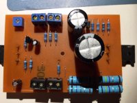
I have attached the PCB, I have the feeling there is an error in it, but can't find it, I guess I am becoming blind for my own drawing..
The only thing I changed was that I switched the resistor R13 and the power LED
My initial look only confirms there is nothing obviously wrong... I will take more time later to go over it and the components again.
Did you use 'real' 2SK170 jfets for Q4 or an alternative?
Alan
Thank you Alan, i used the exact components, except for two resistors. I substituted R10 for a 330k and R12 for 39k, since the 332k and 39k2 I could not find easily.

Looks fine, black yellow purple = 047 * 0.01 (silver) 1% (brown)
Layout seems to be good.
Q3, C2 and resistor values ok?
Layout seems to be good.
Q3, C2 and resistor values ok?
Mmmm, i see your point. I just checked and ordered the right values, but my simple multimeter can not accurately measure such low values...

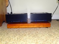
This is the wiring in the box:
View attachment 710169
The soldering work looks bad.
A couple of wires looks like they are not soldered at all.
A black wire from the switch and also the resistor from the switch.
You should let the solder flow so the hole is all filled with solder. All solder joints should be nice round and shinny (no sharp edges). Many looks like "cold" solder joints like you use too little temperature. If you use lead free solder this has higher melting point and is more difficult to work with. Use 60/40 solder......
Thank you Alan, i used the exact components, except for two resistors. I substituted R10 for a 330k and R12 for 39k, since the 332k and 39k2 I could not find easily.
Hi Alan,
i was notified by another DIYAudio member that my Q1-Q4 semiconductors most likely are counterfeits...
So I guess that could be a viable explanation... Do you know of easy to find substitutes for the (hard to find) parts?
Did you find any other possible irregularities (like an error in the PCB or something else)?
Thank you,
Neel
My post 6325 gave the wrong name for the company with the fancy 4 stage professional attenuators. It is Goldpoint. They are not cheap.
Luminous Audio too makes very good passives. Not cheap either but you get some options 😉
I have good experience with Goldpoint. I just used their 24 step attenuator using 0.5% smd thin-film resistors and built it into a box. 24 step is fine.....no really need for 47 step.
Hi Alan,
i was notified by another DIYAudio member that my Q1-Q4 semiconductors most likely are counterfeits...
So I guess that could be a viable explanation... Do you know of easy to find substitutes for the (hard to find) parts?
Did you find any other possible irregularities (like an error in the PCB or something else)?
Thank you,
Neel
First, no I cannot see any obvious mistakes in the PCB.
Radio Spares and Farnell (element14) do the ZTX450 and IRFP240s, I'm sure there must be other reputable Dutch suppliers too. These are not hard to find genuine parts.
The 2SK170 jfet is a bit of a lottery though.
First there are / were only 2 makers: Toshiba = 2SK170 and Linear Systems = LSK170.
Then they come in 3 (or 4) different 'flavours' depending on the IDSS.
You want an IDSS of more than 6mA so try for 2SK170 BL (or LSK170 B). You may find 2SK170 V (or LSK170 C) and these will work fine too. Google and ebay I guess and Not from China!
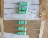
I'm still worried by your 0.47 and 0.68 ohm resistors though. If you cannot measure them, I would replace them with different ones Without the leading Black band.
Luminous Audio too makes very good passives. Not cheap either but you get some options 😉
PLSVN a Luminous Audio box is what I am using in my current system. When you order one of these they "fit" the box to your amp and preamp characteristics, you can choose resistors as well, so it is almost custom made, they will also do a do a burn-in procedure if you wish. This is a very good product, but it is not something you can build into your preamp box, it is a separate totally passive box in its own. I like mine a lot.
I'm still worried by your 0.47 and 0.68 ohm resistors though. If you cannot measure them, I would replace them with different ones Without the leading Black band.
Not being able to measure accurately is a decent indication that they are >10ohm, so that works in his favor
Also, using this chart as a reference, the code makes sense -
An externally hosted image should be here but it was not working when we last tested it.
Anyone know what a leading black band on a resistor signifies?
Umm, I will admit I do not understand why there needs to be an extra Black band on a resistor. As it signifies a 0 (zero) so is unnecessary surely?
So that made me wonder if it is there to move the decimal point one more to the left perhaps?
For instance how would you colour code a 0.068 ohm resistor?
0.68 is easy, Blue - Grey - Silver = 6 8 times 0.01 = 0.68. But there is no code for a 0.001 multiplier.
And if you cannot measure 0.68 ohms you would not be able to measure 0.068!
My 0.68 and 0.47 ohm resistors are pictured first. Neel's are second, those with an extra Black band.
So has any one any experience of the 'leading black band' and what it signifies? (If anything!)
My other line of thought is that Neel's boards look OK and both worked briefly. Imagine if the resistors were 10 times less in value, the 'bias' would be about 15 amps, in which case they probably work for a short while and then destroy the output FETs...
Attachments
- Home
- Amplifiers
- Pass Labs
- Amp Camp Amp - ACA