Makes sense. What's odd too is my nose feels weird, almost a little sore, for a while afterwards
I had a chance to compare a 50W Parts Express Lpad side-by-side with 25 W and a 12.5 W Ohmite rheostats.In my experience, the 50W rms (Ed: Lpad rating) refers to the total loudspeaker system power.
A tweeter only gets roughly a 10% share of the total amplifier power, so can be level controlled without fear of the L-pad overheating.
The "50W" Lpad is considerably bigger and heavier than the 25W rheostat, which in turn is considerably bigger and heavier than the 12.5W rheostat.
The Ohmite rheostats specify max. power dissipation and max. allowed current right on the body of the rheostat. For example, the 12.5W, 10 ohm rheostat is stamped both with "12.5W", and with "1.118 A". If you run 1.118A into a 10 ohm resistor, you get 12.5W (within roundoff error), so Ohmite is making it very clear that yes, this really is rated at 12.5 W.
Since all three items are made of similar material (ceramic substrate, resistive wire), all three have similar specific heat capacity and thermal emissivity. So we can reasonably expect the largest and heaviest to handle the most power.
(There are a lot of flavours ( see Resistance Wire & Ribbon | Coil elements, resistance wire, kilns, foam cutting | Resistance Wire | A Division of Hyndman ) of resistive wire for heating elements, but I doubt that makes a major difference to the power handling capacity of an L-pad or open-frame rheostat.)
There is some black plastic around the Parts Express L-pad, while the two Ohmite rheostats have their internals fully exposed to the air. This would give a slight edge to the Ohmite's in the cooling department.
Nevertheless, it's pretty clear that the "50W" Lpad is not, in fact, rated for only 10% of that power, which would be only 5 watts. It appears to be honestly rated for something well north of 25W.
-Gnobuddy
Thanks for sharing your hands-on experience. The Parts Express L-pad is obviously more substantial than the ones I have handled.I had a chance to compare a 50W Parts Express Lpad side-by-side with 25 W and a 12.5 W Ohmite rheostats.
I would be wary of asking it to dissipate 50W rms continuously though!

Having found out many years ago just how hot a 10W resistor gets if you try to put 10 W into it, I quite agree! 🙂I would be wary of asking it to dissipate 50W rms continuously though!
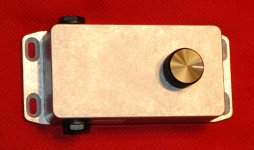
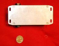
I just finished building a little attenuator around the 12.5 W Ohmite rheostat. I figure it will handle my little 2 W 6AK6 push-pull amp, and probably anything up to Champ territory, say 5 W RMS. It's built into a little Hammond box of the size typically used for guitar FX pedals, roughly 60 mm x 110 mm, or 4 1/4"x 2 1/4".
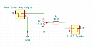
Input impedance is close to 8 ohms with the rheostat at full and an 8 ohm speaker. At other settings, input impedance is between 8 and 10 ohms, depending on speaker impedance and rheostat setting. Output impedance is always close to 39 ohms, plus or minus about two or three ohms.
-Gnobuddy
Attachments
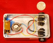
That looks really neat! I see you have adopted the T-pad arrangement, using the single rheostat and a fixed resistor, in order to maintain an (almost) constant impedance to both the amplifier and the loudspeaker.I just finished building a little attenuator around the 12.5 W Ohmite rheostat.
It's worth pointing out that an L-pad control, like the one from Parts Express, actually consists of TWO rheostats. One rheostat is in series with the loudspeaker while the other is in parallel with the loudspeaker, and their resistances vary inversely as the wiper is turned.
Used on its own, an L-pad control will present a constant impedance to the amplifier but NOT to the loudspeaker. Clear photos and a useful calculator for fixed resistor values and, crucially, power ratings are to be found on this site:
L-PADS
However, I would encourage guitarists to adopt your circuit rather than simply use an L-pad control on its own.
Exactly!I see you have adopted the T-pad arrangement, using the single rheostat and a fixed resistor, in order to maintain an (almost) constant impedance to both the amplifier and the loudspeaker.
A few years ago, before I'd twigged to the fact that valve guitar amps have high output impedance, and that this affects the speaker frequency response audibly, I'd made a couple of "L" attenuators with fixed-value power resistors, and a couple of switches to select different amounts of attenuation.
There were two problems with that setup: first, some "tone suck" at high attenuation levels, and second, that annoying issue of never having exactly the right amount of attenuation. One switch setting would be a bit too loud, the next a bit too quiet.
In this thread, both JMFahey's "3 AM Attenuator" (post #9) and John DH's work (post #18) pointed the way to what I thought was an elegant solution: Make the first two resistors in the "Tee" one single rheostat, so attenuation is continuously adjustable, rather than stepped. And make the second resistor much higher value than the rheostat, so that varying the speaker level has very little effect on either input or output resistance.
The values I chose provide about 15 dB of attenuation with the rheostat at maximum, and an 8 ohm speaker. So about 160 mW to the speaker with 5W input, or 67 mW to the speaker with 2 W input. I'm hoping this will be properly in midnight apartment guitar-playing territory.
The 39 ohm resistor can be reduced to 22 ohms or so if more power is required, still with only slight change to the input resistance. Output resistance will drop to roughly 25 ohms, but this is still much higher than the DC resistance of an 8 ohm speaker voice coil, so I suspect there won't be much change to bass response.
I have a further refinement of this design in mind. The plan is to implement some switchable Fletcher-Munson loudness compensation for low speaker SPL levels. There will be separate bass and treble boost (both fully passive), each with its own on-off switch, so you can boost either bass, or treble, or both, or neither, as you choose.
LTSpice simulation looks promising so far, so I may have to build it and try it out to see if it's a worthwhile improvement.
-Gnobuddy
Thanks for the additional technical information re your variable 'T' attenuator.I have a further refinement of this design in mind. The plan is to implement some switchable Fletcher-Munson loudness compensation for low speaker SPL levels. There will be separate bass and treble boost (both fully passive), each with its own on-off switch, so you can boost either bass, or treble, or both, or neither, as you choose.
I look forward to seeing how you go about implementing the refinements quoted above!
yes try that on any resistor! they all will be red hot running full rated power. esp any sand cast power ones, which can melt solder connection and or burn FR4 PCB at half power unless precautions are taken E.g. heat sinks and forced air . Running 15W tube amp full ti8lt with a single musical instrument will be fine.Having found out many years ago just how hot a 10W resistor gets if you try to put 10 W into it, I quite agree! 🙂
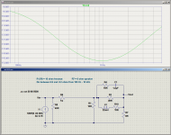
The attached image shows the circuit I plan to build.I look forward to seeing how you go about implementing the refinements quoted above!
L3/R10 produce the bass boost. C1/R4 produces the treble boost. LTSpice doesn't have a switch model (!), but you can imagine an SPST switch in series with C1, and one in series with L3, to allow switching out either part of the EQ.
Current source along with R5 simulate a guitar amp output with 40 ohm source resistance. The 1-milliohm resistor R9 is an LTSpice trick to allow measuring input current into the attenuator, which in turn was used to computer input resistance of the whole circuit (not shown in this screenshot.)
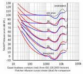
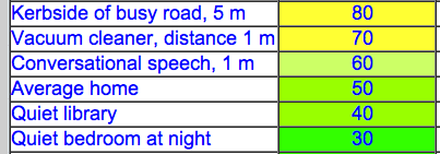
The target bass boost is the loudness compensation from ISO 226, revised 2003 (image from Wikipedia attached.) I'm estimating that usable guitar SPL levels in an apartment are probably between 40 dB ("babbling brook"), and 70 dB ("vacuum cleaner"). Keep in mind there are no guitar frequencies below 80 Hz.
Treble boost is trickier, particularly as guitar speakers peak at about 3 - 3.5 kHz, and then roll steeply off above that. So I'm just taking a wild guess at what might be an appropriate treble boost. Capacitors are cheap, so if it doesn't work, no big loss.
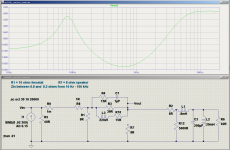
Input resistance is still very well-behaved, between roughly 7 and 8 ohms from 100 Hz - 10 kHz.
Output resistance is no longer as nearly constant as before - but the purpose of high output resistance is to create bass and treble boost, and in this circuit, even as the output resistance falls, additional bass and treble boost are being applied.
Will it sound good? I don't know until I try it. My guess is that the bass boost will be welcome, but I'm less sure about the treble boost.
-Gnobuddy
Attachments
May be my failing eyesight, but I don't see R8 - where's the 'T' gone?
Or, are you modelling for the wiper at the top of its travel?
Or, are you modelling for the wiper at the top of its travel?
Last edited:
Sorry, yes, that particular screen-capture was done with the wiper at full-up.Or, are you modelling for the wiper at the top of its travel?
There are only very slight changes in frequency response with rheostat setting, because the source impedance from a 10 ohm rheostat (fed by a 40 ohm source) is quite low compared to the 39 ohm leg of the "Tee".
LTSpice doesn't seem to have a built-in potentiometer element. I've modelled them with two resistors for a while, but that doesn't look like a potentiometer on a schematic. I also tried to follow a Youtube video on making your own LTSpice potentiometer model, but I must have done something wrong, because one of my pot parameters disappeared along the way. I'll get it right one of these days.
Frequency response isn't by any means an exact match to the ISO loudness standard curves, but is in the general ballpark.
I found reasonably priced 22mH, ferrite-core inductors at one of the usual suppliers. Current and frequency ratings seem quite adequate for this particular application.
-Gnobuddy
No, I'm sorry!
I was a bit slow on the uptake and it only dawned on me what you'd done after I had posted my first sentence - the second sentence was added in the edit!
At least it should be apparent that I'm following with interest!
I was a bit slow on the uptake and it only dawned on me what you'd done after I had posted my first sentence - the second sentence was added in the edit!
At least it should be apparent that I'm following with interest!
Nice project! A few observations come to mind:
The -15db max volume, with a 2W amp gives about 60mW. On my designs, my lowest setting is -27db, running with my 40W amps, which is 80mW. Very close. Im finding that's a good setting for quiet playing, though Im going into 12" greenbacks so speaker efficiency needs to be mixed into that comment. For very quiet use, Ive got another -7db stage available, but I find the MV on the amp is enough generally to tweak from there.
On the modelling, I note the issues with potentiometers in LTSpice. Ill put in a plug for the program I use, which is 5Spice, which is a free download. You can have pots and sweep them 0-100%. Its also a somewhat cleaner looking more modern drag/drop interface.
Ill be interested to see how your FM circuits turn out when you try them. I haven't gone there myself, I find that give Im using big-amp speakers, Im very happy with just a good linear tone response, with the high output Z to let the bass and treble develop.
I target 20ohm output Z from the attenuators, to match that measured from my Vintage Modern. My other amp has no NFB circuit, and has a higher output Z, maybe 50 ohm. Measured and calculated, using 12" speakers (8 ohm with L= 0.35mH), there's about a 1db difference in high treble and bass peak in speaker response changing from a 20 to a 50ohm output.
I've been modelling the speaker reactance too, usually using Aikens equivalent. If you added that to the Spice model, maybe it would show some additional interactions with the FM circuit?
Good luck!
ps - Im still messing around with a reactive front end on my designs, and Im still finding that provided the simple resistaive impedances are controled, as you and I are doing, the reactive parts make virtually no difference even though I can use them to let the amp 'see', very close to a real speaker impedance. If it makes any difference at all, its when the power stage is driving very hard, but its not really much different, or actually 'better'.
Last edited:
Thanks for your comments, John!
Unable to use either of my guitar amps, I was experimenting with an old Jensen speaker and a DIY audio function generator, when I made the shocking (to me) discovery that I could very clearly hear ten microwatts of sinewave power at 1 kHz. 😱
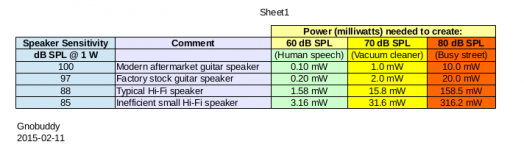
Convinced I'd made a mistake, I decided to do a little math, so I calculated the SPL that would be produced if you drove 10 microwatts into a 95 dB/W speaker. The answer turns out to be 45 dB SPL at 1 metre.
I looked up online loudness tables of everyday sounds, and 45 dB was compared to things like "babbling brook" and "moderate rainfall". Quiet, sure, but very definitely audible.
Okay, no mistake. We really can hear a guitar speaker driven with only a few microwatts of power. That was an eye-opener, so it got me thinking about low-power guitar amps.
Referring again to those loudness tables, I decided that apartment-friendly SPL levels would probably be between 40 dB and 80 dB, roughly corresponding to the SPL of light rainfall, and very loud traffic, respectively. 40 dB for midnight, 80 dB - maybe - if it's daytime on a holiday weekend, and your neighbours are very easy-going.
The next step was to convert some of those SPL levels into the corresponding amount of power you'd need to drive a speaker to get that SPL, assuming various efficiencies. The results shocked me, because they were orders of magnitude lower than any guitar amp you could buy. The two attached images show some of what I found.
-Gnobuddy
A few years ago, I moved from the USA to Canada, in the process having to give up our detached house, and settle for an apartment with people living on every four sides of us....about 60mW....80mW....good setting for quiet playing...
Unable to use either of my guitar amps, I was experimenting with an old Jensen speaker and a DIY audio function generator, when I made the shocking (to me) discovery that I could very clearly hear ten microwatts of sinewave power at 1 kHz. 😱
Convinced I'd made a mistake, I decided to do a little math, so I calculated the SPL that would be produced if you drove 10 microwatts into a 95 dB/W speaker. The answer turns out to be 45 dB SPL at 1 metre.
I looked up online loudness tables of everyday sounds, and 45 dB was compared to things like "babbling brook" and "moderate rainfall". Quiet, sure, but very definitely audible.
Okay, no mistake. We really can hear a guitar speaker driven with only a few microwatts of power. That was an eye-opener, so it got me thinking about low-power guitar amps.
Referring again to those loudness tables, I decided that apartment-friendly SPL levels would probably be between 40 dB and 80 dB, roughly corresponding to the SPL of light rainfall, and very loud traffic, respectively. 40 dB for midnight, 80 dB - maybe - if it's daytime on a holiday weekend, and your neighbours are very easy-going.
The next step was to convert some of those SPL levels into the corresponding amount of power you'd need to drive a speaker to get that SPL, assuming various efficiencies. The results shocked me, because they were orders of magnitude lower than any guitar amp you could buy. The two attached images show some of what I found.
Thanks for the suggestion! LTSpice certainly has some weaknesses. The thing is, I can't stand Windows...so I've been all-Linux at home since 2001. I can get LTSpice to run on Linux, but I don't know if I can get 5Spice to do so. I might give it a try, though.I'll put in a plug for the program I use, which is 5Spice
I have no idea if this will turn out to be an improvement or not, but I figured it was worth spending a few bucks to find out.I'll be interested to see how your FM circuits turn out when you try them. I haven't gone there myself
As a matter of fact, I already did this. After staring at the rather dramatic EQ curves I got, and thinking about the fact that an actual guitar speaker rolls off treble drastically above 3.5 - 4 kHz or so (which isn't reflected in the impedance plot), I decided I couldn't really interpret these curves, so I didn't post them here before. But I'll attach one of them to this post, for whatever it's worth.I've been modelling the speaker reactance too...If you added that to the Spice model, maybe it would show some additional interactions with the FM circuit?
-Gnobuddy
Attachments
At the weekend I did some more impedance tests on my amps. These were at low singal levels, less than 1V amp output. I fed in a clean 440hz sine wave, generated by the pc. At the amp output, one jack went to a multimeter on a 2V ac scale, the other went to a resistive load. I used my attenuator as the load, without speaker. In this way, I can change the resistance from 8ohms to 15.3ohms, nearly a factor of 2. I was concerned about offering such a missmatch to an 8ohm amp tap, but figured its ok given im driving it only to a small output, and monitoring it.
So, with the Vintage Modern (2x KT66), changing to the higher load impedance increased output voltage almost in direct proportion, suggesting an effective output resistance for the amp even higher than I expected. Solving the maths gave an output resistance of the amp of 50 to 60 ohms. The result is very sensitive to the voltage and resistance measurements, but even with significant variations, it was up in that range.
The same tests again on the DSL401 (4x EL84 with no NFB), was 90 to 100 ohm.
Results may be different with different frequencies and greater signals. But it all supports the approach discussed here for keeping output R high in resistive attenuator designs.
Last edited:
Very interesting! So we now have several measurements on several different kinds of valve guitar amps, with output stages varying from single-ended 6V6 to quad push-pull EL84, but all without global negative feedback.Solving the maths gave an output resistance of the amp of 50 to 60 ohms.
<snip>
The same tests again on the DSL401 (4x EL84 with no NFB), was 90 to 100 ohm.
And so far, all output resistances have measured between 40 ohms and 100 ohms.
Even the lowest of those effectively raises the Q of a speaker's fundamental resonance up to nearly Qms. I've only seen Thiele-Small parameters for a handful of guitar speakers, but in all those cases, Qms was in the vicinity of 8 to 10. Meaning there will be a tall, narrow peak in the bass response, not a smooth bass-enhancing EQ bump.
Merlin Blencowe suggests that tube guitar amps that do include global NFB, may have as little as 6 dB of it. Randall Aiken suggests a 10 dB upper limit. Those figures would cut the output impedance of the corresponding guitar amp by roughly a factor of two or three respectively.
So we can estimate that many valve guitar amps that do have global NFB may have output resistances in the range of 12 - 50 ohms. Even the lowest of those numbers is about twice the DC resistance of an 8-ohm speaker, which means most of the electromagnetic damping is lost, and the speaker Q will approach Qms. Qms is the (much higher) Q that's set by the mechanical damping in the speaker (rubbery surround, lossy spider, "goop" that might be applied to cone and surround edges, etc.)
The exceptions would be those few valve guitar amps that had ultra-linear output stages. Those probably had much lower output resistances, since the anode resistance of a pentode often drops an order of magnitude when triode-connected or wired for UL operation (which is heavy local negative feedback.)
I've never seen one one of those UL-ouput guitar amps, and it seems they are a fading footnote in music history. There seem to be a number of contemporary amps that can be switched to triode-mode to lower output power, but I can't get my hands on any of them to measure output resistance. It may not be very relevant anyway, because few guitarists seem to like the sound of triode output guitar amps.
Incidentally, today is Thanksgiving in Canada. So Happy Thanksgiving, everyone!
-Gnobuddy
Some more numbers to digest (and to thicken the plot!...)
I wasn't totally happy with my impedance measuring above, since I was measuring with ac voltages on a multimeter. I don't know how it responds to frequencies. So same theory, but amended technique:
I load up some pure sine tones through the amp and into a looping pedal in the FX loop. Im using 440 hz and 3000hz, very clean and low level.
Then, with than running and no other inputs, I load the amp output with resistance and monitor the amp output back through a clean mixer into audacity. That way I can see the traces, and calculate relative db levels to within 0.1db with et software, about 1%.
So, reworking the test from my last post on the VM amp, I got 30 Ohms, at 440hz. This was with amp MV set low at about 3 and presence at 5. But the same test with amp mv set at 6 (loop signal reduced for about the same output), the calculated output impedance drops to 20 Ohms.
Then, repeat at 3000hz. The same 30 Ohm figure at volume 3, but at volume 6, the output impedance dropped down to 5 Ohms.
It is notable on this amp that at low mv settings, the presence control (which is all about the NFB) is ineffective. So I think Im seeing increasing NFB as the MV is advanced, and more of it at high frequencies than at low! The increasing NFB is reducing output impedance.
In all cases above, actual power amp output is low, so no poweramp distortion happening.
OK, was suspicious of that 5 ohm result from yesterday, since it didn't fit the pattern! I think I was clipping at some point, preventing the signal to rise further. So I redid the 3000hz tests, and 6 on the MV, and this time sweeping the presence control. Sweeping the presence audibly and visibly affects the response at this frequency. Higher presence is from less NFB, and we expect higher output impedance, which is what I now got.
Presence 0, output Z = 15 Ohms
Presence 5, output Z = 20 Ohms
Presence 10, output Z = 65 Ohms
Around 20 ohms is also what I was getting with 440hz.
All signals were recording nice smooth sine waves coming back out of the amp.
One can also surmise that the extra treble from increasing a presence control is not just from the reduction of NFB, but also the resulting higher output Z allowing the speaker impedance to boost treble more.
This VM amp has a PPIMV, which is right in the middle of the feedback loop. all frequencies get feedback but the presence control adjusts it for the high frequencies. So at low MV settings, NFB is cut right back, and, we measure higher output Z (30Ohms), not dependent on frequency or presence settings.
All of this gives me some confidence, because I had arrived after much fiddling and testing, and with growing understanding of what was happening, at around 20 Ohms as the best target output Z for my attenuators. It turns out this is a good value to match my target MV setting of about 6 for this amp.
But it may mean that the best attenuator component values to use depend somewhat on the amp type and favoured settings. But at 20 Ohms, it is most of the way there, within a db or so, even if a more perfect value for a given amp is say 50Ohms.
Last edited:
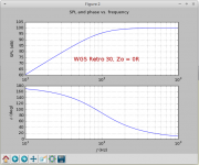
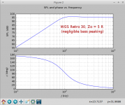
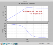
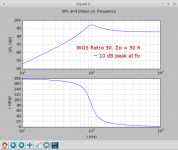
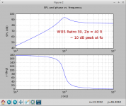
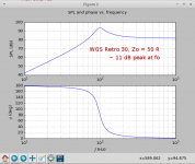
I was curious how much change there is in speaker bass response as the amplifiers output impedance (Zo) continues to rise.But it may mean that the best attenuator component values to use depend somewhat on the amp type and favoured settings. But at 20 Ohms, it is most of the way there, within a db or so, even if a more perfect value for a given amp is say 50Ohms.
We can guess that there will be very little change over a range of rather low Zo values (when Zo << DCR of the speaker), and also very little change over a range of rather large Zo values (when Zo >> DCR of the speaker). But I wasn't sure how big Zo had to be before it stopped having any more influence.
So I ran the series of simulations in the attached images, all using the Thiele-Small parameters that Printer2 posted for the Warehouse Guitar Speakers Retro 30:
Code:
#3----Thiele-Small params for a WGS Retro 30----
v0 = 2.83                #volts, drive voltage, 1 W into 8 ohms
f0 = 98.0                    #Resonance freq, Hz
w0 = 2 * math.pi * f0            #rad/sec
BL = 13.88                #Tesla-metres
m  = 0.02769              #kilos; mms, cone + air
Rs = 6.9                    #ohms
Rs = Rs + 40            #Add 40 ohms amp output impedance (valve guitar amp)
rspkr = 5.5 * 2.54 / 100.0         #12 inch dia speaker, 11 in piston dia, converted to metres
sd = math.pi*rspkr*rspkr        #piston area, square metres
Qms = 15.53                #open-circuit mechanical Q at resonance
k = m*w0*w0            #k is m w0^2, since k/m = w0^2
gamma = m*w0/Qms        #in a mechanical damped osc, gamma = [sqrt(m k)/Q] = m*w0/Q
#--------End Thiele-Small params-----------------------------Gnobuddy
Attachments
-
 WGS_Retro_30_0_Ohms.png47.9 KB · Views: 132
 -
 WGS_Retro_30_5_Ohms.png50.5 KB · Views: 134
 -
 WGS_Retro_30_10_Ohms.png48.1 KB · Views: 85
 -
 WGS_Retro_30_20_Ohms.png49 KB · Views: 83
 -
 WGS_Retro_30_30_Ohms.png46.7 KB · Views: 92
 -
 WGS_Retro_30_40_Ohms.png48.7 KB · Views: 85
 -
 WGS_Retro_30_50_Ohms.png49.3 KB · Views: 79
For bass response, I havnt been using TS parameters, but just the equivalent circuits that people use in load boxes when they set out to model a reactive load with bass resonance. From that, i can see the voltage across the speaker and hence if it changes relatively due to output impedance. Its not actually calculating speaker sound response as in a TS calc, but it should be picking up db differences in the electrical signal. I figure that if the attenuated response has the same shape electrically as the full response, then the actual sound will also be consistent
- Home
- Live Sound
- Instruments and Amps
- Attenuator for a 15W to 25W guitar amp