when i connect a 3.3v source to the ISO 3.3 in pin on the Soekros 1021 everything goes haywire. the Reflektor-D stops functioning and the amanero board disappears from the computer. both function alright when not connected to the soekris board 3.3 in. what does it mean?
I just tried that but with no luck. I got no sound.
It was my first experience with MKROM so I just want to be sure that this filter mod applies to the new rev. 1.19 firmware? And it's just an edited version of the 1021filt_120 txt file?
PM me. I'll send you the .skr file.
what does LRCK stand for? the amanero usb i2s board does not have a pin called lrck so it is nt cleat which pin from amanero should be connected to the iso lrck on the 1021.
LRCK - left right clock
This clock make word select for each channel.
On Amanero this is called FSCLK - frame select clock (same thing different name).
FSCLK from amanero should go to LRCK from Soekris.
Regards,
Tibi
Last edited by a moderator:
when i connect a 3.3v source to the ISO 3.3 in pin on the Soekros 1021 everything goes haywire. the Reflektor-D stops functioning and the amanero board disappears from the computer. both function alright when not connected to the soekris board 3.3 in. what does it mean?
Do not connect a 3,3V to Soekris.
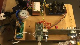
If you want to power amanero froma separate source, Remove L1 from amanero board and power as you can see in attached picture.
The wire that go to C2 is the ground from aux 3,3V regulator.
Using a low noise regulator for Amanero improve performance considerably.
Regards,
Tibi
Attachments

Last edited by a moderator:
LRCK - left right clock
This clock make word select for each channel.
FSCLK from amanero should go to LRCK from Soekris.
Regards,
Tibi
thanks. with this i think that all the connectios are in order and the only issue remaining is the 3.3 volt for the isolator chip on the soekris
PM me. I'll send you the .skr file.
Please change file extension to .pdf and attach here, so more people enjoy your findings.

Regards,
Tibi
as soon as connect the 3.3 volt from amanero to soekris iso 3.3 the amanero disappears from the computer. similarly as soon as i connect the reflektor-d to thd soekris bord iso 3.3 the reflektor d's led turns off and reflektor-d stos functioning. there is something abou the 3.3v iso on the soekris board.
Do not connect a 3,3V to Soekris.
If you want to power amanero froma separate source, Remove L1 from amanero board and power as you can see in attached picture.
The wire that go to C2 is the ground from aux 3,3V regulator.
Using a low noise regulator for Amanero improve performance considerably.
Regards,
Tibi
the soekris biard requires a 3.3 volt iput for the i2s isolatio chip.
/////
soren please help me with this. does this mean that the soekris board is malfunctioning?
Sorry, I was not clear. You need to take 3.3V from amanero.
If your voltage drop when 3,3V is connected to soekris, than I susspect a isolator problem on soekris board.
Regards,
Tibi
If your voltage drop when 3,3V is connected to soekris, than I susspect a isolator problem on soekris board.
Regards,
Tibi
the soekris biard requires a 3.3 volt iput for the i2s isolatio chip.
/////
soren please help me with this. does this mean that the soekris board is malfunctioning?
I doubt there is a problem with the dam1021, they're tested before leaving us and my experience is that 99% of problems is due to cabling.... Sounds like you're shorting something.... Check your wires, maybe post pictures so we can look at your setup....
PM me. I'll send you the .skr file.
Thanks, I appreciate that. Being a newbie when it comes to using MKROM I would still like a copy of the edited txt file. I'd like to be able to use the utility on my own.
Thanks, I appreciate that. Being a newbie when it comes to using MKROM I would still like a copy of the edited txt file. I'd like to be able to use the utility on my own.
Okay I got it now. I was using the old vers. 0.85 of MKROM since I wasn't aware there was a new 0.99 version of the utility as of april 2018.
Attachments
Last edited:
I doubt there is a problem with the dam1021, they're tested before leaving us and my experience is that 99% of problems is due to cabling.... Sounds like you're shorting something.... Check your wires, maybe post pictures so we can look at your setup....
absolutely. i have no doubt that the boards are tested well. it is possible that i made a short without knowing sometime in the past. in the etup now i dont see any shorts or problems and i have checked everything. I will post picturs soon but if there ss in fact damage to the board. is there any fixes or repairs or should i just throw it away?
Last edited:
I doubt there is a problem with the dam1021, they're tested before leaving us and my experience is that 99% of problems is due to cabling.... Sounds like you're shorting something.... Check your wires, maybe post pictures so we can look at your setup....
i double checked. i removed eveery connection except tge 3.3v and as soon as it is connected the amanero stops functioning so the short has to be on the board. all the voltages at j2 are correct. so i only have the +-12 provided at j1 and i read the voltages at j2 and all are correct but when i provide the 3.3 to pin 13 at j3 it is a short.
Last edited:
even when the soekris 1021 board is not powered at all, the problem persists. i checked with my muktumeter and the connection between the isolated 3.3v and any other isolated groubds next to it is a hard short that is there even when the board is not powered.
physically i see no imperfections or problems. and my soldering joints also look very good if i may say so i i have to conclude that i probably made a short at some point that fried or killed the isolation board without any ohysical evidence. soren is there any solutions or is this board beyond hope?
serial number is 002023. would you help me soren?
i removed the board from every physical connection. just the board itself and pin 13 on the j3 boards in a physical short with every other isolated ground pin.
serial number is 002023. would you help me soren?
i removed the board from every physical connection. just the board itself and pin 13 on the j3 boards in a physical short with every other isolated ground pin.
Last edited:
physically i see no imperfections or problems. and my soldering joints also look very good if i may say so i i have to conclude that i probably made a short at some point that fried or killed the isolation board without any ohysical evidence. soren is there any solutions or is this board beyond hope?
serial number is 002023. would you help me soren?
i removed the board from every physical connection. just the board itself and pin 13 on the j3 boards in a physical short with every other isolated ground pin.
You could sent it in for repair, but I would probably have to charge you....
Since there are so few parts on the isolated side, you could try debugging it yourself.... If possible, connect a low voltage high current source (could be a 1.5V battery) to the power pin, then whatever get hot is defect. If that's not possible, lift the power pins on the three isolator chips one by one, pin1 on two of them and pin8 on the middle one, until there is no short anymore, then you have the defect chip. It could be a shorted capacitor, but that's not that likely.
is it possible to use the spdif input if i buy the az lite board that audiozen sells?
/////////////
i do not want to mess with smd parts since i know i will ruin them so i i will send it to you for repair.
is it possible to use the spdif input if i buy the az lite board that audiozen sells?
/////////////
i do not want to mess with smd parts since i know i will ruin them so i i will send it to you for repair.
I mean using the az lie board and is did it in the current condition without repair?
- Home
- Vendor's Bazaar
- Reference DAC Module - Discrete R-2R Sign Magnitude 24 bit 384 KHz