checking up
Wayne;
Yes, I desoldered them and ordered a new pair from Mouser.
When I stuffed the PCB last spring I went down all the caps and resistors on a roll and missed the optocoupler being flipped .
It was apparent checking my board while looking over the build guide though. 🙂
Wayne;
Yes, I desoldered them and ordered a new pair from Mouser.
When I stuffed the PCB last spring I went down all the caps and resistors on a roll and missed the optocoupler being flipped .
It was apparent checking my board while looking over the build guide though. 🙂
If you purchased one of the NABU chassis enclosures from Surplus Sales for $30 shipped .The WHAMMY board fits right on three of the standoffs that are already in the enclosure for the OEM board I stripped out of it. 
I just have to drill a hole for the fourth mounting hole on the WHAMMY board and it's good to go.
I removed the 2 heat sinks from the rear of the NABU and their mounting holes line up exactly for the mounting holes 2 large body Neutrik RCA input jacks I have. I just have to drill out a circle for the jack
High DC Offset!
I just finished my WHAMMY and so far all I'm getting out of it is very high DC offset regardless of the op-amp used.😡
It ranges anywhere from 1.5V to almost 7V.
With no op-amp, it measures 130mV.
PS voltages are +/- 15.06V.
Using 10 ohm resistors for bias. Was using 20 ohm but the outputs' sinks felt cool to the touch.
Any ideas why such high offset?
Thanks.
Hmmm.... Check for bad solder joints and that the optocouplers are in the right way.
More importantly, post some well-lit, in-focus photos so we can take a look for the issue.
More importantly, post some well-lit, in-focus photos so we can take a look for the issue.
Hmmm.... Check for bad solder joints and that the optocouplers are in the right way.
More importantly, post some well-lit, in-focus photos so we can take a look for the issue.
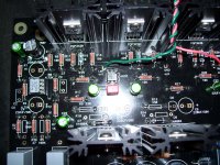
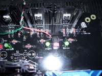
Here are a couple of photos. My apologies since my old Kodak doesn't make the best close-up photos.
I don't think I have any bad joints since I used a hot Weller iron and took the time to solder all components from both sides, but it's still a possibility.
Attachments
Are there insulators on the output mosfets?
No, I didn't think they were needed since the sinks are isolated from the board.
In the first page of this thread, Jim stated that they weren't needed.
how about with no op amp in the socket. it should be better DC wise and will bias up.
Offset drops to around 130mV for both channels with no op-amp. As soon as I place a op-amp in the socket, bias jumps right back up.
I went by the values silkscreened on the board for component placement instead of the schematic.
Hopefully, there aren't any component placement errors on the board.
First, the opamp input is not referenced to ground because R3 and R5 are empty. They need to be stuffed with 100K. I bet that will fix your problem.
There's also a chance the opamp is oscillating or doing something strange because there's not local rail decoupling... Put some caps, anything you have, in the empty C3 C4 positions. 0.1uF film, 10Uf electrolytic, whatever. Value isn't actually going to matter much in that position.
You are correct, there are no insulators needed for the mosfets (assuming the heatsinks are not touching any part of the chassis.
First, the opamp input is not referenced to ground because R3 and R5 are empty. They need to be stuffed with 100K. I bet that will fix your problem.
Jim, you're the MAN!
Installing the 100k resistors fixed the problem and brought the offset down to only a few millivolts.
I didn't think they were really needed since they could actually increase the offset of bipolar op-amps because of such a large difference between the impedance of the noninverting input vs. the inverting input.
Thanks.
LEDs Take Different Times to Go Out
All,
Back from holiday and I finally found the time to replace D6 in front of the 7815 regulator. I now have -16.9V from the 7915 regulator and 16.60V from the 7815 regulator. Is a 0.3V difference OK ?
When I turn the amp off D5 in front of the 7915 regulator takes 17 seconds to go out, whereas D6 in front of the 7815 regulator takes over 2 minutes to go out. Did I blow up something else as well as the LEDs ?
Regards
Mark
6L6, Wayne & Zen Mod
Diode and LED replaced in front of the 7915 regulator - red light now on and -16.88V on the output. Thanks for your help. I can now replace the diode and LED in front of the 7815 and get back to zeroing the DC offset of the LM833 !
All,
Back from holiday and I finally found the time to replace D6 in front of the 7815 regulator. I now have -16.9V from the 7915 regulator and 16.60V from the 7815 regulator. Is a 0.3V difference OK ?
When I turn the amp off D5 in front of the 7915 regulator takes 17 seconds to go out, whereas D6 in front of the 7815 regulator takes over 2 minutes to go out. Did I blow up something else as well as the LEDs ?
Regards
Mark
0.3v difference is fine.
Don't worry about the LEDs extinguishing. Many circuits have different current draws on the rails. Plus, if you are looking at this under no load, it's essentially meaningless.
Carry on.
😀
Don't worry about the LEDs extinguishing. Many circuits have different current draws on the rails. Plus, if you are looking at this under no load, it's essentially meaningless.
Carry on.
😀
LED Extinguishing Times
6L6,
Thanks for the quick response. I am a newbie to this kind of detail, so I probably don't have the whole story, but I would have thought that the time for the LEDs to extinguish is basically a function of the amount of energy stored in the caps at switch off, and the 'size' of the LEDs it has to dissipate through. As the LEDs are near enough identical, and both 'halves' have the same capacitance, I would heve thought the discharge times would be similar, not a factor of 10 different. Moreover, before I shorted the LEDs and replaced the regulators, diodes and LEDs, the time for the LEDs to extinguish was pretty much the same - hence my concern that I may have damaged another component somewhere else.
Regards
Mark
0.3v difference is fine.
Don't worry about the LEDs extinguishing. Many circuits have different current draws on the rails. Plus, if you are looking at this under no load, it's essentially meaningless.
Carry on.
😀
6L6,
Thanks for the quick response. I am a newbie to this kind of detail, so I probably don't have the whole story, but I would have thought that the time for the LEDs to extinguish is basically a function of the amount of energy stored in the caps at switch off, and the 'size' of the LEDs it has to dissipate through. As the LEDs are near enough identical, and both 'halves' have the same capacitance, I would heve thought the discharge times would be similar, not a factor of 10 different. Moreover, before I shorted the LEDs and replaced the regulators, diodes and LEDs, the time for the LEDs to extinguish was pretty much the same - hence my concern that I may have damaged another component somewhere else.
Regards
Mark
LM 833 DC offset
All,
As previously posted using the 'standard' 100 kohm values for R3 and R5 and an LM833 opamp gave me a 24mV no load DC offset. As suggested above I used various resistors and a trimmer from my spare parts box to zero the no load DC offset for the LM833 at 6.1 kohm for R3 and R5. The nearest value I had in the spares box was 5.1 kohm which gives a no load DC offset of -0.2 mV, which is near enough. This might be worth adding to the beginning of this thread for newbies like me who in ignorance assumed that any of the opamps listed as having been 'tried with great success' could be used without any changes to the values in the schematic 🙂
I have bought another 4 LM833 opamps and I will see if there is any significant variation in the DC offset when I get some time.
Thanks again for the help.
Regards
Mark
I think what Wayne is saying is that the input bias current on the LM833 will flow through the 100K resistor on the + input pin. The inputs are PNP as shown on the datasheet so the bias current will flow out of that pin and create a positive offset voltage on the pin. The typical bias current is about 300nA. Flowing through the 100K resistor gives a typical offset of 30mV, which isn't far from the 24mV you measure. You can reduce the input resistor to reduce the offset, change to a different op amp with lower input bias current, or add a DC servo circuit to cancel it out.
All,
As previously posted using the 'standard' 100 kohm values for R3 and R5 and an LM833 opamp gave me a 24mV no load DC offset. As suggested above I used various resistors and a trimmer from my spare parts box to zero the no load DC offset for the LM833 at 6.1 kohm for R3 and R5. The nearest value I had in the spares box was 5.1 kohm which gives a no load DC offset of -0.2 mV, which is near enough. This might be worth adding to the beginning of this thread for newbies like me who in ignorance assumed that any of the opamps listed as having been 'tried with great success' could be used without any changes to the values in the schematic 🙂
I have bought another 4 LM833 opamps and I will see if there is any significant variation in the DC offset when I get some time.
Thanks again for the help.
Regards
Mark
At the moment I am planning the assembly of the Whammy headphone amplifier. So far I have only built loudspeakers. This project will be my first entry into the world of electronics. Therefore the following questions arose for me.
1. Is the bill of material mentioned on the first page complete?
2. Are the pictures and texts still valid for the newer PCB revisions?
Due to my limited experience in the field of electronics, I do not dare to derive the individual production steps independently.
Best regards
Alex
1. Is the bill of material mentioned on the first page complete?
2. Are the pictures and texts still valid for the newer PCB revisions?
Due to my limited experience in the field of electronics, I do not dare to derive the individual production steps independently.
Best regards
Alex
At the moment I am planning the assembly of the Whammy headphone amplifier. So far I have only built loudspeakers. This project will be my first entry into the world of electronics. Therefore the following questions arose for me.
1. Is the bill of material mentioned on the first page complete?
2. Are the pictures and texts still valid for the newer PCB revisions?
Due to my limited experience in the field of electronics, I do not dare to derive the individual production steps independently.
Best regards
Alex
Yes, go for it...be careful, there are 3 configurations, please read about them carefully and plan accordingly. If in doubt, ask the forum
Two questions (perhaps of many):
The RCA jack's grounds are attached to safety earth via that orange capacitor. Am I just missing it on the BOM or is it just some random capacitor that isn't specified? If so... what should I use for it?
Also, I don't understand that much about power supplies, so the phrase "If you add a power switch, switch the Live lead." doesn't mean anything to me. I do have a power switch on mine. How do you know which was the live lead to begin with? I can't actually see how the transformer and the IEC Inlet are wired based on those pictures and since I can't test the power supply until I have done those things, I'm kind of at an impasse.
Thank you.
- Home
- Amplifiers
- Pass Labs
- "WHAMMY" Pass DIY headphone amp guide