Hi Lawrence.
As I think I mentioned in the thread somewhere, this was all designed and built before I had a PC and that is why no original artwork for the PCB's exists. It was all drawn and finalised on paper before being copied over to the bare copper clad board.
Advantages, well that's the easy one... it just sounds so right. Totally unfatiguing and offering tremendous insight with pretty much most source material. On the original -/+45v rails its good for 70 wrms into 8 ohms from its single pair of single die laterals.
Actual measured distortion is an unknown although simulations suggest sub 0.01% @ 70wrms and around 0.001% @ 1watt.
Hi Lawrence.
As I think I mentioned in the thread somewhere, this was all designed and built before I had a PC and that is why no original artwork for the PCB's exists. It was all drawn and finalised on paper before being copied over to the bare copper clad board.
Advantages, well that's the easy one... it just sounds so right. Totally unfatiguing and offering tremendous insight with pretty much most source material. On the original -/+45v rails its good for 70 wrms into 8 ohms from its single pair of single die laterals.
Actual measured distortion is an unknown although simulations suggest sub 0.01% @ 70wrms and around 0.001% @ 1watt.
looks to be very good....can someone step up make the pcb files so we can send off for a small run of boards, and a BOM so we can buy the parts
Lawrence
I used the pcb layout in post #300. Very nice, but needs a bit more space around it for mounting holes. Also a bit tight around the 0V faston.
I have only one pair of FETs fitted per channel. Also needs the PCB outline track cutting to avoid shorting the rails.
If it lacks a bit of power on my 40V rails I might add another pair of FETs and up the rails to 56V. I suspect it will then need the VAS and current source transistors replacing with TO126. Think I've got some vintage 2SA1360 and 2SC3423s which would probably do very micely.
If you read back through the thread, you find reference to previous PCB suggestions by other members, including AlexMM. There's a more recent offering at #564. I figure that if you really are interested, you'll at least scan back and glean the interesting stuff anyway.looks to be very good....can someone step up make the PCB files so we can send off for a small run of boards, and a BOM so we can buy the parts.....Lawrence
... it just sounds so right. Totally unfatiguing and offering tremendous insight with pretty much most source material.
I have had mine running for an hour of so. First impression are that I agree... just like baby bear's porridge!
 and I'm sure that the more you listen and the more it will grow on you.
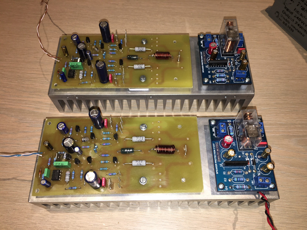
Member
Joined 2009
Paid Member
I am just resurrecting my MJR7 Mk5s to do a comparison:
MJR7-Mk5 Mosfet Power Amplifier
However this pans out, the Mooly amp is something special!
MJR7-Mk5 Mosfet Power Amplifier
However this pans out, the Mooly amp is something special!
The MRJ has been resurrected.
I also have a P101, an Akitika and a MyRef FE (audiophile build) built up at the moment.
Unfortunately my NAP200 clone and GB150 need to use the same PS as the Mooly amp, so direct comparisons are not possible.
The PS uses a very nice pair of EI transformers with (Quasimodo'ed) C-RC snubbers, which I'm sure helps the sound.
The Mooly amp is very fine indeed!
Will it stop me building more amps? On sound quality, it really ought to!
The only minor niggle I have with this amp is that the gain is about double the ideal for my system.
I usually use feedback values of 22K and 1K wherever possible to give a voltage gain of X23.
I am wondering if it would be OK to reduce R14 to 10K to give a gain of just over X22?
Trouble is, this doubles the feedback factor. I then thought of reducing R10 to 3K3 to keep roughly the same feedback factor, but I don't think this will work because it doubles Q1 collector current (to ~400uA) and therefore halves Re and restores the original gain :-(.
So, is there a good way to reduce the gain of this amp?
Dave,
You can judiciously insert local fb at the input and the VAS stages to hold the global fb at the same level as you decrease the closed loop gain.
Alternatively, you can put in nested fb from the VAS back to the fb node.
I will check out the circuit and then chat with Karl but this is all doable.
Hugh
Dave,
You can judiciously insert local fb at the input and the VAS stages to hold the global fb at the same level as you decrease the closed loop gain.
Alternatively, you can put in nested fb from the VAS back to the fb node.
I will check out the circuit and then chat with Karl but this is all doable.
Hugh
Eagerly waiting for the outcome !🙂
Thanks for the interest guys.
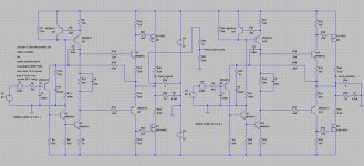
The only realistic way to alter the AC gain would be via the feedback return resistor which is the 470 ohm (R7). Changing the 22k feedback resistor upsets the whole DC operating point, changes the current in Q1 and alters the operating point of the TL071 although that should be able to maintain the correct bias point.
So you can try increasing R7 to suit, however increasing R7 and leaving its series 470uF will increase the settling time of the amp and so really the cap should be changed (lowered in value) to maintain the same sort of time constant.
Untested changes are always to difficult to predict, the big question is whether you feel the tonality is altered by changing the feedback factor... interesting 🙂
Thanks for the replies and great to hear (read) from Hugh!!
Here's a possibility:
R7 470R -> 1K
C2 470uF -> 220uF
Add a 120R emitter resistor to Q1 (great idea Hugh!)
Here's a possibility:
R7 470R -> 1K
C2 470uF -> 220uF
Add a 120R emitter resistor to Q1 (great idea Hugh!)
Dave,
Try a 680k metal film from the collector of T3 back to the emitter of T1, that is, across C7.
That will set the global feedback at the ratio of 680k/22k = 31, which corresponds to 29.8dB of fixed global feedback for the original circuit.
Adding 120R emitter to Q1 would not do it here because this is a singleton, not a LTP. Increasing the 22k series fb resistor increases the closed loop gain and reduces global feedback, but you want to reduce the gain. So if you reduce the 22k to say 15k, I'd use a 470k nested fb resistor.
I mention all this because nested feedback has particular benefit and and I will leave it to you to find out what it is.......
Hugh
It will work very well with your reduced gain.
I think the additional emitter resistor on Q1 will work...
OLG of Q1 is set by R10 (6K8) / re (effective emitter resistance)
re ~=Ic/25mA i.e. 125 Ohms at 200uA
Adding an external 125R emitter resistor will halve the gain, and improve the linearity due to local feedback (probably by exactly the same amount as the global f/b would do if the gain was left as original).
Anyway, I like your nested feedback approach better!
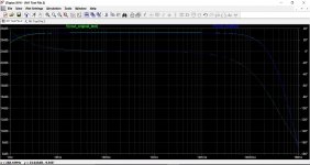
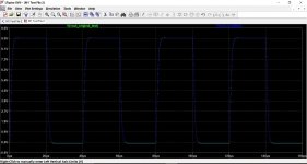
I had a little play with this in simulation, and (with the proviso that untested modifications can not be guaranteed) found the stability of the design such that it is pretty much unfazed by whatever you throw at it.
This shows the original and modded lower gain version done simply by raising the feedback return from 470 ohm to 1k and reducing the 470uF down to 330uF. The results speak for themselves. Even removing the input filter resulted in virtually no difference between the two versions.
I've attached the dual amp file so anyone can play around with this. The output of the original amp is taken from a resistive divider so that the two gains can be equalised and the traces overlaid for comparison.
Attachments
- Home
- Amplifiers
- Solid State
- My MOSFET amplifier designed for music