This one uses Nchannel Vfets and 3 Power supplies...How about Pch device as the previous one.
This will eliminate OPT and directly coupled and maybe sound better and more efficient than SE.
This will eliminate OPT and directly coupled and maybe sound better and more efficient than SE.
This one uses Nchannel Vfets and 3 Power supplies...How about Pch device as the previous one.
This will eliminate OPT and directly coupled and maybe sound better and more efficient than SE.
Yes, it may be used complementary devices and use the P-channel vfets 😀
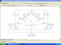
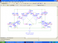
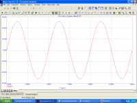
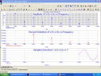
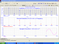
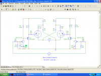
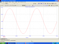
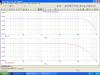
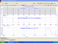
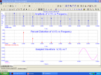
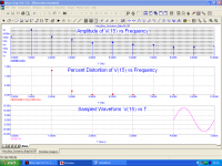
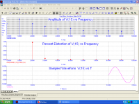
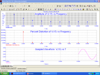
In the following an example to build such a 15 Watt amplifier in class AB.
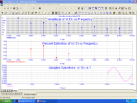
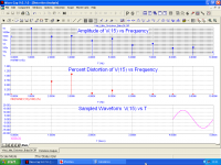
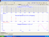
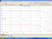
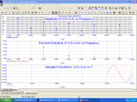
Attached images for schematic, Transient, AC, and Distortion Analisys for 15,10,5,1 W/8 Ohm
Attachments
-
 Little_Circlotron_BabySit.png41 KB · Views: 450
 -
 Little_Circlotron_BabySit_Transient_Analisys.png38.6 KB · Views: 441
 -
 Little_Circlotron_BabySit_AC Analisys.png41 KB · Views: 421
 -
 Little_Circlotron_BabySit_ Distortion_Analisys_15 W.png48 KB · Views: 408
 -
 Little_Circlotron_BabySit_ Distortion_Analisys_10 W.png50.2 KB · Views: 400
 -
 Little_Circlotron_BabySit_ Distortion_Analisys_5 W.png48.2 KB · Views: 101
 -
 Little_Circlotron_BabySit_ Distortion_Analisys_1 W.png47.7 KB · Views: 106
this looks like better now...another good option for us, if i'm going to use 3 identical 36v supply will the power dissipation and power out will be higher?
this looks like better now...another good option for us, if i'm going to use 3 identical 36v supply will the power dissipation and power out will be higher?
You must look at the Voltage pressure on the input Jfets. Normal Jfets are limited to 50 V max. If you use either 36V PSU you are out of their limits, and so you need a High Voltage Jfets like 2SK373 or more exotic types. P types are however pratically unobtainable, this explain the values chosen for PSU.
Attachments
okay i get it...i have 80V Jfets close to K373...so maybe i can increase the all the rails to 36v or 35v all. Do i need to change some resistor values?
okay i get it...i have 80V Jfets close to K373...so maybe i can increase the all the rails to 36v or 35v all. Do i need to change some resistor values?
Yes it depends on voltage used, output power and class of amplifier (A, AB).
You need also either high voltage and high gm Jfets.
Hybrid Circlotron
Here the Hybrid schematic with all N devices (tubes and Vfets) for 100 Watt class AB Circlotron.
Pictures are for Schematic, Transient, AC and Distortion analisys for 100, 50, 10, 1 Watt/8 Ohm
Here the Hybrid schematic with all N devices (tubes and Vfets) for 100 Watt class AB Circlotron.
Pictures are for Schematic, Transient, AC and Distortion analisys for 100, 50, 10, 1 Watt/8 Ohm
Attachments
-
 Tubey_Circlotron_BabySit.png47.5 KB · Views: 199
 -
 Tubey_Circlotron_BabySit_Transient_Analisys.png41.5 KB · Views: 172
 -
 Tubey_Circlotron_BabySit_AC_Analisys.png40.3 KB · Views: 95
 -
 Tubey_Circlotron_BabySit_Distortion_Analisys_100 W.png51.5 KB · Views: 102
 -
 Tubey_Circlotron_BabySit_Distortion_Analisys_50 W.png50.5 KB · Views: 87
 -
 Tubey_Circlotron_BabySit_Distortion_Analisys_10 W.png50.4 KB · Views: 91
 -
 Tubey_Circlotron_BabySit_Distortion_Analisys_1 W.png50.3 KB · Views: 94
The Blue Circlotron
A version of average power with P-channel Vfets , such as a desire to Junm, with the variant of 4 psu.
We did a long series on possible uses of the same type of Vfets in push pull circuits .
I believe that is enough.
You must note also that all circlotron schematic presented here have voltage gain.
I am attaching pictures of this last version for schematic, transient, ac, and distortion analiys at 50,20,10,5,1 Watt / 8 Ohm.
Thank you all
Francesco.
Attachments
-
 Blue_Circlotron_BabySit.png44 KB · Views: 174
 -
 Blue_Circlotron_BabySit_Transient_Analisys.png39.4 KB · Views: 162
 -
 Blue_Circlotron_BabySit_AC_Analisys.png41.2 KB · Views: 107
 -
 Blue_Circlotron_BabySit_Distortion_Analisys_50 W.png47.9 KB · Views: 103
 -
 Blue_Circlotron_BabySit_Distortion_Analisys_20 W.png49.2 KB · Views: 98
 -
 Blue_Circlotron_BabySit_Distortion_Analisys_10 W.png49.4 KB · Views: 91
 -
 Blue_Circlotron_BabySit_Distortion_Analisys_5 W.png49.6 KB · Views: 93
 -
 Blue_Circlotron_BabySit_Distortion_Analisys_1 W.png50 KB · Views: 91
Last edited:
Thanks Mos57 for patience and doing such lot of simulation for me and to rest who got interest on this...
It time to start something..actually i had started doing it but stop due to influx of more interesting schema's you feed in... I will again review all the schema's and select the one that will suit my available parts now ...still awaiting my Jfets ordered weeks ago...
It time to start something..actually i had started doing it but stop due to influx of more interesting schema's you feed in... I will again review all the schema's and select the one that will suit my available parts now ...still awaiting my Jfets ordered weeks ago...
Hello, I have revived this thread since I had collected some parts and trying to continue to build and test the schematics posted in this thread but first I just want to ask some questions again, I don't like to burn my SITs so i'm asking this questions., patience pls...
What parameters (Vgs,Vds,Idss etc) to match for Vfets for Parallel mode (2SJ18's rank JG-57)?
When matching this devices do I need to put heatsink on the DUT(VFet)?
Do someone kind enough share or give me schematics for matching Vfets?
Its my first time to match Vfets so I don"t know if its the same as BJT's. I have 13 J18 to match for since this are just 63w Max Dissipation.
I found some 2SK60 rank 34 and 2Sj18 rank 24....my question is does Sony made those ranks... i thought ranks 51-58 are the only originals..
The stocks are clean and shiny, the seller said that it was given by him by his Japanese friend together with some K176 and J50 which i think are all originals. MY only doubt is on the k60 and j18 ranks ...Anybody have an Idea?
The stocks are clean and shiny, the seller said that it was given by him by his Japanese friend together with some K176 and J50 which i think are all originals. MY only doubt is on the k60 and j18 ranks ...Anybody have an Idea?
Could anybody say, what are the typical values of output impedance for the schematics present at this thread?
I found some 2SK60 rank 34 and 2Sj18 rank 24....my question is does Sony made those ranks... i thought ranks 51-58 are the only originals..
The stocks are clean and shiny, the seller said that it was given by him by his Japanese friend together with some K176 and J50 which i think are all originals. MY only doubt is on the k60 and j18 ranks ...Anybody have an Idea?
Only the last digit is the rank number. The previous two letters and first digit is a batch code. There is no reason why these would not be originals.
HOWEVER - the current fad among dealers in china is to sell whatever you ask them for by stripping the markings of what they have, and stamping on what you want (usually simple inkjet print that wipes off with alcohol). It is quite possible you would get actual VFETs, just the rank and also type may be something completely different and not what you thought it was. So, buyer beware.
Thanks....so these are "4 " matched rank , so I will proceed to purchase his remaining stocks around 20 pairs...
I had compared my original stocks with those and seems no variance from the casing assembly and prints are are very clear and intact with some has little rusty like look that indicate how long it has been staying on his warehouse.
I don't Buy parts Online or e-bay since most of them are imitation or fakes...
I'm also suffering the V-FET fever so I want to revive this thread.
I already have two single ended SITs (SK82 and SK180) and I plan to add a differential amplifier input to the bigger one. I will try to repair a Sony TA-5650 and build a V-FET version of the VSSA from Lazy Cat.
But appart from that I want to explore other possibilities and profit to learn how amplifiers work in the process. 🙂
Please see attached concept schematics for balanced input amplifiers and tell me what do you think. Will they work? What improvements can be made to them?
The aims for these are simplicity and good sound, given that the SITs are already low distortion units.
Please bare in mind that I don't know about what I am talking about and be nice.
Cheers.
M
Attachments

Hello Max, welcome to our world.
I come back here after a long time.
I have not yet done your circuit simulation, but I'm sorry to tell you that your circuit will not work mainly because of two major flaws.
If you want to use one SEPP scheme you should look at the Yamaha B1 amplifier circuit to get an idea.
Have you thought that with the 2sk180 you may also get more than 50 watts in single ended?
If you have devices in one polarity, have you thought to use circlotron scheme or output transformer?
See also my website, there are many ideas about it.
Francesco
I come back here after a long time.
I have not yet done your circuit simulation, but I'm sorry to tell you that your circuit will not work mainly because of two major flaws.
- while the voltages of the two upper and lower Vfet require two rather different Vgs values, the outputs of the differential input will instead be approximately at the same voltage.
- the Vgs voltage of lower Vfet evidently will result with positive polarity while the Vfet needs a Vgs with negative polarity.
If you want to use one SEPP scheme you should look at the Yamaha B1 amplifier circuit to get an idea.
Have you thought that with the 2sk180 you may also get more than 50 watts in single ended?
If you have devices in one polarity, have you thought to use circlotron scheme or output transformer?
See also my website, there are many ideas about it.
Francesco
I'm also suffering the V-FET fever so I want to revive this thread.
I already have two single ended SITs (SK82 and SK180) and I plan to add a differential amplifier input to the bigger one. I will try to repair a Sony TA-5650 and build a V-FET version of the VSSA from Lazy Cat.
But appart from that I want to explore other possibilities and profit to learn how amplifiers work in the process. 🙂
Please see attached concept schematics for balanced input amplifiers and tell me what do you think. Will they work? What improvements can be made to them?
The aims for these are simplicity and good sound, given that the SITs are already low distortion units.
Please bare in mind that I don't know about what I am talking about and be nice.
Cheers.
M
Last edited:
Ciao caro Francesco,
Sorry for the late reply and thank you very much for your interest and advices.
About bias, wouldn't and external independent (-)bias generator connected to G and S circumvent the flaw?
I am used to think in voltages to ground, that's why I err.
I love singled ended and the next obvious step would be comparing the plain R load version to the CCS version with a Mosfet as the active load and then with another 2SK180 as active load, just to see if there is a difference soundwise. And being there, I would study if there can be some form of positive feedback applied, as dynamic contrasts are one of preferred traits in musical reproduction.
I've always wanted to build a circlotron but the issue of the multiple power supplies (and fear) stopped me. I remember you posted some circuit with less PSs...
I studied Yamaha B1's schematic but didn't understand much. I would love to get a simplified version of it, now that there are still some big V-FETs, comparable to the SK77, around... 😱
Cheers,
Mauricio.
I'm just about to wake this thread but here it is...awaken..
2SK180 are interesting big Vfet...i just hope you can come up with a good working design. I also have 2sk182es in the waiting..
2SK180 are interesting big Vfet...i just hope you can come up with a good working design. I also have 2sk182es in the waiting..
I'm just about to wake this thread but here it is...awaken..
2SK180 are interesting big Vfet...i just hope you can come up with a good working design. I also have 2sk182es in the waiting..
Assuming you can give the high input capacitance a good drive, look at the Yamaha B1 for inspiration on using these...
- Status
- Not open for further replies.
- Home
- Amplifiers
- Solid State
- What to do with this Sony V-FETS?