I would like 1 x pcb if available Prasi? Thanks for your efforts 🙂
Hello bix,
if the requirements go to about 20, then its possible to have economical single sided pcbs manufactured here. otherwise it is not economical. or i can post gerbers, but still would be costly for single person even from china (pcbway says usd 62 with cheapest shipping).
regards
Prasi
That's and impressive list of amps.
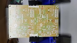
some were designed (PCB) and fabbed by me and some are donated by kind members.

Almost done.
R8 47R
R16, R17 jumpers
T3 2SB861
T4 2SD1138
I shall use TIP35C for outputs.
Nicely done Ivan, looks pretty neat!
2-3 questions
Any particular reason why base stoppers are eliminated in your build?
Also what is the value of C10 you are using? ok. got it 2200uf🙂
what PSU you plan use? (just for info)
regards
Prasi
Edit: sim and thimios build give a value of 15k for R5.
Last edited:
I think that base stoppers will not be needed for this amp, that the amp will be stable without them.
C10 is 2200uF. In my opinion it's beneficial to use lower values especially if loudspeakers are close to walls and corners. The same opinion had John Linsley Hood.
PSU will be 50V SMPS that forum member BC109 gave to me free of charge.🙂 It's OK to use SMPS if you have one.
C10 is 2200uF. In my opinion it's beneficial to use lower values especially if loudspeakers are close to walls and corners. The same opinion had John Linsley Hood.
PSU will be 50V SMPS that forum member BC109 gave to me free of charge.🙂 It's OK to use SMPS if you have one.
In general, having output series cap is beneficial for small rooms and close to wall or corner loudspeaker placement, meaning boomy bass. Output cap will provide small low frequency rolloff that will tame problematic boomy bass.
C10 is 2200uF. In my opinion it's beneficial to use lower values especially if loudspeakers are close to walls and corners. The same opinion had John Linsley Hood.
PSU will be 50V SMPS that forum member BC109 gave to me free of charge.🙂 It's OK to use SMPS if you have one.
Hi Ivan,
Interesting about C10. I too will have to give that a try.
Just wondering what current rating your SMPS has? I've got a 48v power brick that I intend on using and wonder if 1.6A is enough.
Hello Boyet,
Here are the files. All the best for your build. Do post here when you build and test it.
regards
prasi
Thank very much Prasi. Well keep you posted.
Member
Joined 2009
Paid Member
Using output cap to roll off bass means worse case electrolytic distortion. Better to have output cap corner frequency at least a decade below lowest frequency of use. Instead use input cap to roll off bass, where a small value high quality cap is more affordable.
thanks bigun, I had already ordered 6800uF Nichicon for o/p, they will get to pass some music after all 😉 .
with 1uf coupling and 100k (to gnd) at the input, the -3dB point is ~1.6Hz
and at the o/p, with 6800uF and 8 ohm load, its ~2.9Hz.
So should be ok.
do you suggest to use something like 220nF or 470nF at the i/p with 7.2Hz and 3.4 Hz as -3dB points?
regards
Prasi
with 1uf coupling and 100k (to gnd) at the input, the -3dB point is ~1.6Hz
and at the o/p, with 6800uF and 8 ohm load, its ~2.9Hz.
So should be ok.
do you suggest to use something like 220nF or 470nF at the i/p with 7.2Hz and 3.4 Hz as -3dB points?
regards
Prasi
Last edited:
First test
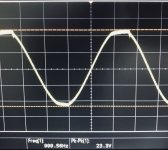
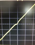
First test and no smoke, phew. Stuck with the original schematic as you can see by the crossover distortion. Running off 33V DC, spare toroidal from an old amp.
Next I’ll replace R5 to 15K as suggested. Still need to sought out bias setting also. Looking good so far 🙂
First test and no smoke, phew. Stuck with the original schematic as you can see by the crossover distortion. Running off 33V DC, spare toroidal from an old amp.
Next I’ll replace R5 to 15K as suggested. Still need to sought out bias setting also. Looking good so far 🙂
Attachments
Using output cap to roll off bass means worse case electrolytic distortion. Better to have output cap corner frequency at least a decade below lowest frequency of use. Instead use input cap to roll off bass, where a small value high quality cap is more affordable.
The whole point in building these old topologies is to replicate old sound with all its idiosyncracy and distortions, not to compete with modern ultralinear amplifiers. In that sense using lower value output cap will not spoil anything.
First test and no smoke, phew. Stuck with the original schematic as you can see by the crossover distortion. Running off 33V DC, spare toroidal from an old amp.
Next I’ll replace R5 to 15K as suggested. Still need to sought out bias setting also. Looking good so far 🙂
I think that with this old topology you can not use any supply voltage as you can with modern topologies. You should use 50V.
First test and no smoke, phew. Stuck with the original schematic as you can see by the crossover distortion. Running off 33V DC, spare toroidal from an old amp.
Next I’ll replace R5 to 15K as suggested. Still need to sought out bias setting also. Looking good so far 🙂
Looking good Bix!
Let the fun begin..
Attachments
I think that with this old topology you can not use any supply voltage as you can with modern topologies. You should use 50V.
Thanks Ivan, appreciated. I’ll be running 50V ASAP, just couldn’t wait. 😉
Cheers Avtech, have fun mate. That pcb holder looks pretty handy.
First test and no smoke, phew. Stuck with the original schematic as you can see by the crossover distortion. Running off 33V DC, spare toroidal from an old amp.
Next I’ll replace R5 to 15K as suggested. Still need to sought out bias setting also. Looking good so far 🙂
Hello Bix,
nicely done, is that a bit of oscillation I see on the hills or just the clipping behaviour?
regards
Prasi
- Home
- Amplifiers
- Solid State
- Retro Amp 50W Single Supply