Just began testing my newly assembled F5 kit with Universal Power Supply and Deluxe 4U chassis. Blows fuses on power-up. Power supply tested fine before connecting to amp boards. Removed and inspected amp boards and found R1 (4.75K) and R2 (47.5K) flipped. Repaired and began test with only one board wired. Quick power-up with meters connected and I see 2.8V across both R7 and R8 so I quickly shut down. Also about 15V at output! Tried the other board alone and same result.
Just bought parts for a light bulb tester. So, I will have that as test tool shortly.
Have built electronics since 13 years old when I became a ham (now 68). Good soldering skills.
Things I've checked and double checked:
all resistors in the right place
orientation of Q1 & Q2, 2SK170 & 2SJ74
orientation of Q5 & Q6, ZTX550 & ZTX450
orientation of Q3 & Q4, IRFP9240 & IRFP240
Q3 & Q4 are not shorted to ground through the heatsink
power supply +24V and -24V right on
Any ideas for the next steps to troubleshoot would be most appreciated.
Thanks in advance for any guidance and advice.
Wil
Some people advise after 300VA a thermistor I would definitely use something at 500VA especially if the amp biased into Class A. Also depends on how much capacitance use at your PS. Usually, we use a lot of capacitance at Class A building so a soft start would eas the power surge stress.
Some people advise after 300VA a thermistor I would definitely use something at 500VA especially if the amp biased into Class A. Also depends on how much capacitance use at your PS. Usually, we use a lot of capacitance at Class A building so a soft start would eas the power surge stress.
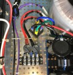
Using two CL60 in series with 115V primary per build plan. Problem is that there should be no voltage across R7 & R8 until bias is set. Both pots, P1 & P2 are set at maximum resistance (5K ohm), fully CCW and I see ~2.8V instead of 0V. Also ~15V at speaker out which should also be 0V. Something is very wrong.
Attachments
for starters , both drain pots need to be at bloody minimum ..... zero...... nada........ zilch
As ZM said, you want P1 and P2 to start at 0, which turns off the output devices.
Then you slowly increase them while monitoring voltages across R7 and R8 and
offsets...
Then you slowly increase them while monitoring voltages across R7 and R8 and
offsets...
for starters , both drain pots need to be at bloody minimum ..... zero...... nada........ zilch
I've never built one of these and the thread is really long but looking at the schematic on page 9 shouldn't R1 and R2 be 10ohm resistors as well? The 4.7k resistor w the thermistor and the 47k resistors for the gates of the output mosfets? I just like reading other peoples issues to try and learn how to go about trouble shooting and fixing them.
Last edited:
page is user/browser dependent , so you need to link to exact post , or at least write down exact #number of post
page is user/browser dependent , so you need to link to exact post , or at least write down exact #number of post
post #89
http://www.diyaudio.com/forums/pass-labs/121228-f5-power-amplifier-9.html#post1484933
and I guess it should be 47ohm to the gates not 47k
Last edited:
I've never built one of these and the thread is really long but looking at the schematic on page 9 shouldn't R1 and R2 be 10ohm resistors as well? The 4.7k resistor w the thermistor and the 47k resistors for the gates of the output mosfets? I just like reading other peoples issues to try and learn how to go about trouble shooting and fixing them.
Definitely no 47K resistors anywhere on schematics....
EDIT: I see you edited your post, what is fitted ?
Last edited:
What schematic are you using?
Version 3 board from DIY Audio store.
Attachments
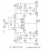
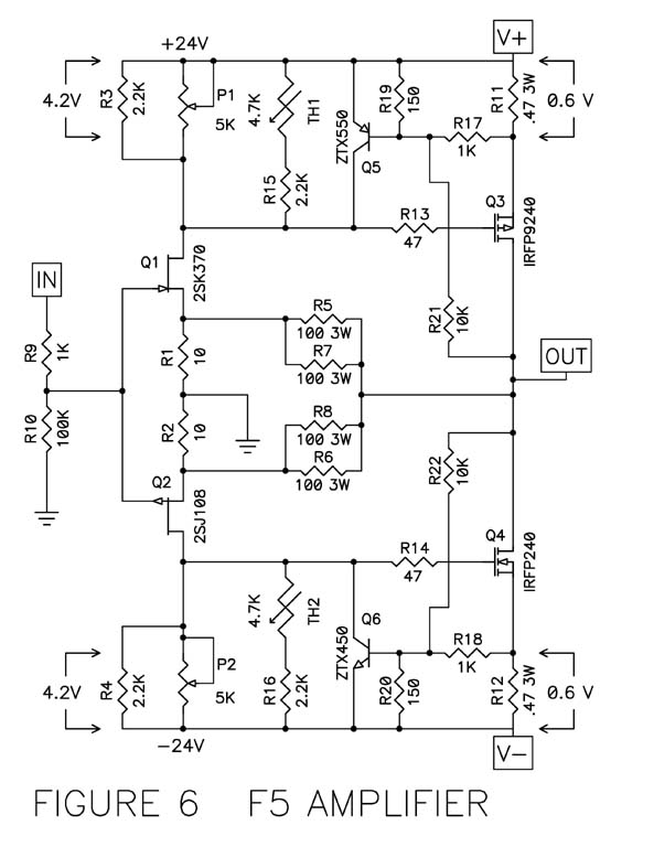
from post #89 (schm attached)
Ra and R2 are 10R ( each)
mosfet gate resistors are 47R each (R13 and R14)
in fact , observe that numbers without suffix are for Ohms , all other having approporiate suffix K for KiloOhms
NB that there is later iteration , with P3 added in sources of input JFets , for altering THD spectra and lesser demands for matching of active parts
for starters , both drain pots need to be at bloody minimum ..... zero...... nada........ zilch
Just for clarification, zero ohm or 5K ohm to begin bias settings?
The build guide says to turn pots fully CCW to start bias setting which should give you zero volts across R7 and R8. So, I have pots positioned as in the pictures and turned pots fully CCW but I get 2.8V across R7 and R8 instead of zero.
from post #89 (schm attached)
Ra and R2 are 10R ( each)
mosfet gate resistors are 47R each (R13 and R14)
in fact , observe that numbers without suffix are for Ohms , all other having approporiate suffix K for KiloOhms
NB that there is later iteration , with P3 added in sources of input JFets , for altering THD spectra and lesser demands for matching of active parts
ok thank you. When the previous poster had commented
" Removed and inspected amp boards and found R1 (4.75K) and R2 (47.5K) flipped."
I was confused and thought that may be were theyre having some issues
Turned P1 and P2 fully clockwise (not CCW as stated in build guide) and bias adjustment fell into place. Bias set with zero offset. Ready for some music.
Thanks Zen Mod!
Thanks Zen Mod!
CW or CCW is thing I'm often remembering for second or two ; I'm used to believe in my instruments , not my memory
so , for proper setting operation ,connect as many DMM you have , prepare coffee or tea , relax and enjoy in process.
Assembly of Japanese bicycle require great peace of mind
🙂
learning new trick/thing or two is for me more exciting than (having) entire new amplifier .......
so , for proper setting operation ,connect as many DMM you have , prepare coffee or tea , relax and enjoy in process.
Assembly of Japanese bicycle require great peace of mind
🙂
learning new trick/thing or two is for me more exciting than (having) entire new amplifier .......
Last edited:
Hi All - this is my first post on Diyaudio.
I just finieshed first channel of F5 and powered it up. Everything was going smoothly, bias setting and DC off set are good but when I connected speaker an played music there is no sound. Any idea what might have gone wrong? Were should I start the troubleshooting?
I just finieshed first channel of F5 and powered it up. Everything was going smoothly, bias setting and DC off set are good but when I connected speaker an played music there is no sound. Any idea what might have gone wrong? Were should I start the troubleshooting?
Were should I start the troubleshooting?
If you have no test equipment it may be tricky.
Check the wiring of the RCA jack. Post some photos.
- Home
- Amplifiers
- Pass Labs
- F5 power amplifier