Switching between spdif and I2S is just done with a simple switch on SW1😛OS1.
If you want more than one SPDIF input (say up to 4) you will want a 4:1 analog switch/mux prior to the spdif input. You could also use custom firmware and use other inputs (like GPIO) as SPDIF - but that is advanced stuff. Switching is simpler.
If you want more than one SPDIF input (say up to 4) you will want a 4:1 analog switch/mux prior to the spdif input. You could also use custom firmware and use other inputs (like GPIO) as SPDIF - but that is advanced stuff. Switching is simpler.
Thanks. How does one conveniently add a switch for switching between the buffalo’s SPDIF input and the i2c inputs? SW1 is hard mounted to the board, so is there a pinout elsewhere on the board that overrides this?
Again apologies if this is basic stuff explained elsewhere it’s not super clear in a way I would understand.
Again apologies if this is basic stuff explained elsewhere it’s not super clear in a way I would understand.
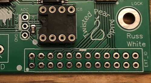
The ext header is there for that purpose - just leave the dip switch open (switch in off position) for SW1-1.
You just need to wire an external switch from that pin(pin 5 - SW1-1) to GND.
See here:
Buffalo III SE (Stereo Edition) Pro
You just need to wire an external switch from that pin(pin 5 - SW1-1) to GND.
See here:
Buffalo III SE (Stereo Edition) Pro
Last edited:
Superb... thank you, so I switch off the dip switch onSW1 and then hook a spst to pins 1 and 2 (on the dotted pin and the one above it...)
In future I can add a Muxer/switch board to the spdif input on the BIIIpro and then switch between the i2c and spdif inputs so I can switch to i2c from any spdif input setting.
In future I can add a Muxer/switch board to the spdif input on the BIIIpro and then switch between the i2c and spdif inputs so I can switch to i2c from any spdif input setting.
Last edited:
Actually you want to connect the switch to pin 3(GND) and 5(SW1-1). See the chart on the link.
You have the right idea. 🙂
You have the right idea. 🙂
Ah yes, I see that pins 1 and 2 are conjoined... thanks... i’ll get a single spdif working and then expand it when I have it. Thanks for your help.
One last question for anybody... How much current would you guess is required to hold pin 8 of the DAC high? What is typical 'these days'? [I'm considering an analog solution here - an RC pair that charges in 2 seconds...]
An update with observations about I2C on the 9028 - FYI in case anybody wants to try this. Pin 8 of the DAC, accessed through GPIO position 1 on the B3sePro board, draws a surprising amount of current to hold high. It is 5v tolerant and I have an Arduino mini sending 5v to three separate B3sePro boards. No resistor in the Arduino->Pin 8 connection and the voltage still drops to 3.8. Bottom line: I2C is working AND contrary to the data sheet, the chip address is 0x48 just as with the es9018. Significant DAC control software debugging must still happen before I get to listen in earnest...
Frank
Easy digital volume, easy SPDIF/I2S switch... ES9018 made easy!
Mine is the 9038 and it’s just such a big difference in terms of separation and clarity to the raspberry pi DACs I have been using for these past few years. The latest one I have been using is an Allo Piano 2.1 DAC and one of the better ones and clearly inferior to the Buffalo DAC in every way possible.
Very satisfying to make work with the Kali as well... off to order a Muxer now... then get the case made and tidy the wires... at present it’s a bit... well... functional... LOL.
 Untitled by Claire Fox, on Flickr
Ps is there any benefit to using two placid PSUs? Instead of joining the Placid outs?
Last edited:
I have bitten the bullet and ordered a Mux unit and switch and I am looking at the diagram and scratching my head. So time for another simple question...
How does power get into this system?
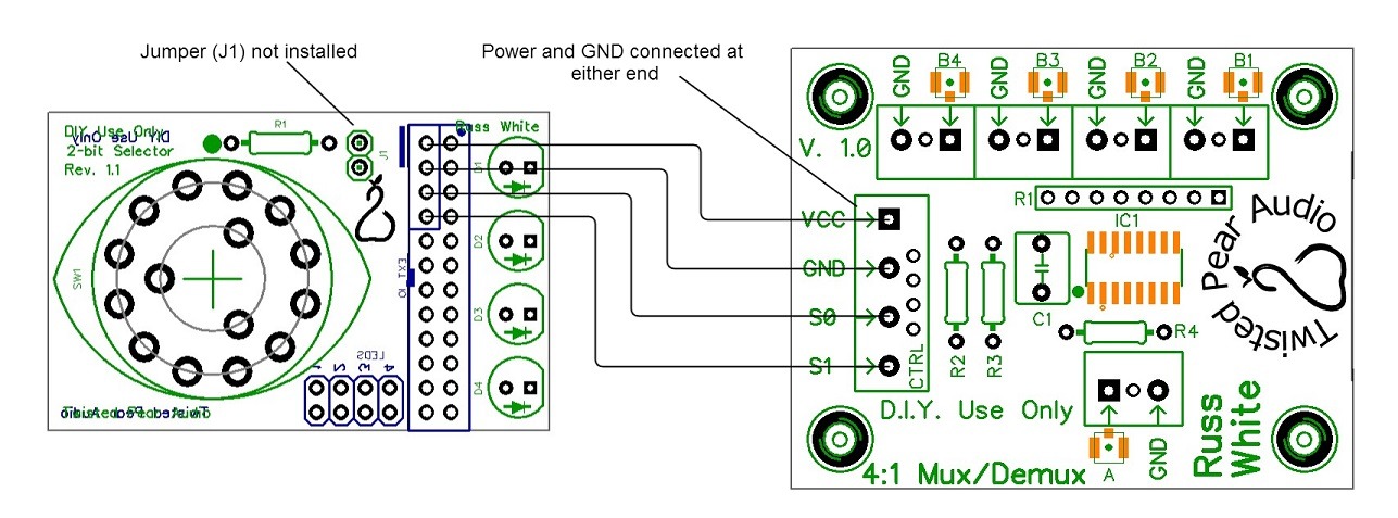
I see the boards are connected together via VCC pin 2 and GND pin 4 (on the reverse of the board) but how does the 3.3V-5V.25V power get into this board? I have a spare 5V supply so I am good to go when it arrives.
And what is J1 for?
How does power get into this system?
I see the boards are connected together via VCC pin 2 and GND pin 4 (on the reverse of the board) but how does the 3.3V-5V.25V power get into this board? I have a spare 5V supply so I am good to go when it arrives.
And what is J1 for?
Last edited:
An update with observations about I2C on the 9028 - FYI in case anybody wants to try this. Pin 8 of the DAC, accessed through GPIO position 1 on the B3sePro board, draws a surprising amount of current to hold high. It is 5v tolerant and I have an Arduino mini sending 5v to three separate B3sePro boards. No resistor in the Arduino->Pin 8 connection and the voltage still drops to 3.8. Bottom line: I2C is working AND contrary to the data sheet, the chip address is 0x48 just as with the es9018. Significant DAC control software debugging must still happen before I get to listen in earnest...
Frank
It is probably dropping to 3.8V because of a protection diode - or you have some series resistance.
Datasheets sometimes include the RW bit as part of the address. Just shift 🙂
Glad you are enjoying it! 🙂Mine is the 9038 and it’s just such a big difference in terms of separation and clarity to the raspberry pi DACs I have been using for these past few years. The latest one I have been using is an Allo Piano 2.1 DAC and one of the better ones and clearly inferior to the Buffalo DAC in every way possible.
Very satisfying to make work with the Kali as well... off to order a Muxer now... then get the case made and tidy the wires... at present it’s a bit... well... functional... LOL.
Ps is there any benefit to using two placid PSUs? Instead of joining the Placid outs?
As for separate I/V supplies - you will get slightly better channel isolation.
Cheers!
Russ
It is probably dropping to 3.8V because of a protection diode - or you have some series resistance.
Datasheets sometimes include the RW bit as part of the address. Just shift 🙂
Thanks Russ! Listening now. With default setup, the drop-in 9028s are more than I hoped for. Tighter bass, better overall neutrality, clarity and detail. Also less sibilance from my finicky midrange drivers when they encounter diva sopranos. 🙂 Based on what I'm hearing, the Legatos are very much up to the task and remain a great choice for the 9028s.
Further comments on I2C control and the tweaking process will go to this thread, which previously related to the es9018:
Control of BBB-based audio appliances
Russ and Brian, fine fine work!

Frank
I have bitten the bullet and ordered a Mux unit and switch and I am looking at the diagram and scratching my head. So time for another simple question...
How does power get into this system?
I see the boards are connected together via VCC pin 2 and GND pin 4 (on the reverse of the board) but how does the 3.3V-5V.25V power get into this board? I have a spare 5V supply so I am good to go when it arrives.
And what is J1 for?
J1 was added to allow using one position to trigger another switching unit. Originally it was for Sidecar (used with the older 8-channel Buffalo), but could be used with an OTTO or 4:1 Mux.
This year will se many ES9018s orphans. Or in the Swap Meet thread 😉
How this can be? 🙂 I have BIII with 9018 and Legato and it is such a good DAC I can't believe there can be anything significantly better, something you can hear during music playback. (even from Russ and Brian)
Seems it's the case! Better Tridents and better DAC chip: every builders said there is an improvement. Hard to imagine I agree =) Anyway it's an improvement of even better of the very best, calling for top speakers and amp...
I have a spare placid working and I was going to try separately powering the Mercury left and right sides. Am wondering if there is enough current in the 50VA traffo to use with a second placid by jumpering the two boards at the corresponding AC secondaries or if I really need to get another matching traffo for this?
I'm preparing to upgrade my sync-mode 9018 dual mono rig to a dual mono 9028 hopefully running in syncmode. Brian kindly included the dual mono firmware on a chip for me and I will use this initially but I'd like to take advantage of the syncmode firmware too.
@Russ is the syncmode firmware option included within the dual mono firmware? Or, how can I amalgamate the two?
I've bought the sparkfun programmer and a few chips - I've even managed to program a chip with the arduino IDE and make the LED flash (very proud moment) but I'd be grateful if anyone can point me to an idiots guide to getting started with what software to use to dump one of Russ's hex files onto those chips with the tiny programmer?
Cheers,
Crom
I'm a neophyte as far as doing this as well but I managed to get things working. You'll need AVRDude software. I used twluke's post he submitted after programming the new firmware to get an idea what the command line should look like and substituted the usbtiny device for the one he used in the example provided. My command line looked like this "avrdude –pt85 -cusbtiny -Pusb -u -Uflash:w:"Buffalo-3-SE-Pro-OB-SyncMode-PCM_DSD.hex":a -Ulfuse:w:0xE2:m -Uhfuse:w:0xD5:m -Uefuse:w:0xFF:m".
The chip programmed without errors and my output was identical to his. The hex file needs to be in the right location. In my case that was in my Users folder on Windows 10. This won't help with modifying the firmware of course. I'm pretty sure that will take a bit of studying up.
I have a small issue to report though and I'm not sure why my result is different than what others are reporting. Everything works well on PCM up to 384 and DSD works up to 512x48 but I have noise on DSD64 and 128. I'm guessing the quantity of noise halves from 64 to 128 and completely disappears on DSD256. I've tried programming another chip without change and reverting back to the stock firmware restores DSD64 and 128 playback. Could be I missed something. The improvement in sound is in line with what others are reporting.
- Home
- More Vendors...
- Twisted Pear
- Introducing the Buffalo III-SE-Pro 9028/9038