its the amp we are talking about, not the speaker
the amp doesn't have a flat frequency respons with the sonus faber load and the amp will add sparkle and mist with the sonus faber as load
the kef is a different load, the amp!!!!! will have a flatter respons with the kef load and will add less sparkle and mist.
on your scope you'll see less transient ringing and less rising frequency respons when you test your amp with a load like the kef. the kef can have unbearable piercing treble and the sonus faber can sound mellow sweet, I don't know, I only focus on the amplifier part
hi
thanks for your ideas. i do not prefer actually a speakers of mine and the speakers will be modded but not now....its an other project with my brother and friends - they are speakers "experts"
the only speaker which is "finished" is my 12-5 open baffle,which is electrical reduced => 2nd 12"chassis with 10 ohms in series...because of my small room. additionally i add the better Tang Band W3-2141...
Lautsprecher Shop | Dipol 12-5 Bausatz | Lautsprecher Selbstbau
i really like the direct, quick response of OB speakers. 😀
thanks
chris
I still haven't understood your issue/problem you complain about. What are you trying to do/improve?
Isn't everything working as expected?
Isn't everything working as expected?
I still haven't understood your issue/problem you complain about. What are you trying to do/improve?
Isn't everything working as expected?
Hi doctor
in Post #532 i ask if its necessary to change the grey caps (smal grey block caps) to improve the sound....then irribeo give me the hint about the adaptation of amp - speaker.
if the amp is on its sound level "boarder" then it´s ok for me...🙂
Oh, okay. Changing the gray caps (with "better" ones at the same value) in the output filter will pretty much do nothing to the sound. (Technical speaking)
You can adjust the filters corner frequency and also the filters "peaking" by using different values here, but this also wouldn't change much (if at all), as the corner frequency is out of audio band in this configuration.
The question is (subjective), what needs to be improved "in sound"? Is there anything missing/to much... etc.
If yes, it is possible to fix/adapt this by using a simple EQ or DSP? I mean, it is so much easier to adapt the sound to your needs by using EQ/DSP rather than believing in something like "capacitor sound".
These TPA32XX are "best in class" if properly implemented on its own.
Oh, okay. Changing the gray caps (with "better" ones at the same value) in the output filter will pretty much do nothing to the sound. (Technical speaking)
You can adjust the filters corner frequency and also the filters "peaking" by using different values here, but this also wouldn't change much (if at all), as the corner frequency is out of audio band in this configuration.
The question is (subjective), what needs to be improved "in sound"? Is there anything missing/to much... etc.
If yes, it is possible to fix/adapt this by using a simple EQ or DSP? I mean, it is so much easier to adapt the sound to your needs by using EQ/DSP rather than believing in something like "capacitor sound".
These TPA32XX are "best in class" if properly implemented on its own.
Hi doctor
Sorry to asking nooby questions.
thanks to your hints. Yes i know it is not easy to say this amp is ready.
actually i missing nothing,..... "just" to complete my searching for fake or doing something better at this TPA3250 implementation (FX502SPRO)
if you remember to my list of "todo"..... i try to close some issues because i intepret this its not needed.
e.g. you mentoined something like the coils...changeing to shielded onece and not the "aircoils"
chris
Attachments
Last edited:
Yes, aircoils do have a huge electromagnetic field. If you don't get problems with electronics near the amp, leave as is.
I've read, you put 1800uF at the AVDD pin with the result of "improves dynamics and transparency." I'm not sure if this is a good idea for the internal regulator structure due to dI/dt (inrush current into the cap) when powering on. There might be effects caused by electromigration which may result in premature fail. I'd rather suggest to keep the values moderate (up to 10uF X7R 50V Ceramic).
You may try to go back to stock value (1uF) and change the cap-value at C_Start is this is related to the internal feedback loop in some case. Former test showed benefits from increased value at this point. 1uF seems to be quite right here, compared to the standard 10nF.
Please see the attached PDF for infos.
Attachments
Last edited:
Yes, aircoils do have a huge electromagnetic field. If you don't get problems with electronics near the amp, leave as is.
thanks doctor. 🙂
as Irribeo mentioned i will try to start scope measuremnts at the LM317...on the weekend...
Yes, aircoils do have a huge electromagnetic field. If you don't get problems with electronics near the amp, leave as is.
I've read, you put 1800uF at the AVDD pin with the result of "improves dynamics and transparency." I'm not sure if this is a good idea for the internal regulator structure due to dI/dt (inrush current into the cap) when powering on. There might be effects caused by electromigration which may result in premature fail. I'd rather suggest to keep the values moderate (up to 10uF X7R 50V Ceramic).
You may try to go back to stock value (1uF) and change the cap-value at C_Start is this is related to the internal feedback loop in some case. Former test showed benefits from increased value at this point. 1uF seems to be quite right here, compared to the standard 10nF.
Please see the attached PDF for infos.
oohh..thanks doctor...i did not do this...so the green color is wrong!
i just copy paste too fast..😉
As you recommended...i will not do that...!
thanks a lot...
I ordered Feixiang FX AUDIO FX502SPRO HIFI Audio Digital High Power Amplifier Home Mini Professional Amp TPA3250+NE5532 24V 4A 2 Colors-in Amplifier from Consumer Electronics on Aliexpress.com | Alibaba Group chosen because the vender had more orders than others offering the same product hoping for a V5 board. It arrived 10 days later in USA. Its a V3 board, but feel it sounds better than the dual tpa3116 it replaces. I'm happy.
Hi
i did a short ripple measurment at 8 ohms (2,8A) and 4 ohms (5,6 Amp)load at the origianl psu (psu1).
about 220mVpp during load.
Any cheap trick to filter out this? CRC filter?
cu chris
i did a short ripple measurment at 8 ohms (2,8A) and 4 ohms (5,6 Amp)load at the origianl psu (psu1).
about 220mVpp during load.
Any cheap trick to filter out this? CRC filter?
cu chris
Attachments
Hi Chris,
A CRC filter won't work on 50Hz and 2.8/5.6 Amp. The "C"s would need to be huge (and the "R" cause power loss).
The power adapter I assume you use, is simply not fast and precise enough to regulate better. 220mV at 5.6 Amp is actually not bad.
Only a linear regulator, preferably with an emitter output, will do better. Unless, you buy a specific audio SMPS with fast step response and they are hardly cheap.
Hi Chris,
A CRC filter won't work on 50Hz and 2.8/5.6 Amp. The "C"s would need to be huge (and the "R" cause power loss).
The power adapter I assume you use, is simply not fast and precise enough to regulate better. 220mV at 5.6 Amp is actually not bad.
Only a linear regulator, preferably with an emitter output, will do better. Unless, you buy a specific audio SMPS with fast step response and they are hardly cheap.
Hi Fauxfrench
i am very sorry..but after posting a get a hugh update on my laptop.
and i see i did post the wrong pics.....sorry
attached the correct pic...the psu is working good......and its for me ok
Attachments
...sound check with KEF Q100
Hi .
as promised some posts before.
i changed the speakers at the FX502 V3(blue) version.
the sound is much clearer, fresher and focused as the sonus, the bass is good controlled and fine in deepness.
the speakers are nearly the same sensitivity 86_85db/W but the kef are slightly louder then the sonus. the KEf where quite new speakers and i read that a lot of hours are needed to get a fine sound because of the rigid construction of the chassis....this was done the last weeks...
Last edited:
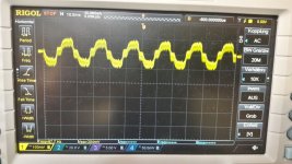
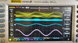
..clipping check... V5 White FX502Spro
I want to know what is the sensitivity and the "right" position of the volume knob. When is the amplifier clipping....?
I tested the white V5 version of the FX502Spro with the original psu (24V ). this amp is not corrected at the LM 317 for 24V out.
i time i use the 28V rigol dp832.
8 ohms load each channel, 1khz 1Vrms in both RCA in. DMM at R channel to measure the amps
from top to buttom
yellow LM317 in
light blue LM317 out
blue is rca in
pink output at + speaker on the L-channel
pic 1 1 Vrms at RCA in - volume knob at 11 oclock
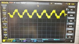
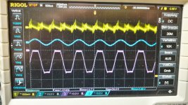
pic 2 2 Vrms at RCA -typical fixed output from a CD player..e.etc..
its clipping at volume knob 11 oclock
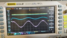
pic 3 2 Vrms at RCA -typical fixed output - no clipping at volume knob 10 oclock
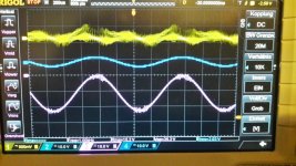
pic 4 1 Vrms at RCA in - volume knob little more then 12 oclock - start clipping. its about 1,789 Amps and 13Vrms ---> about 23 Watts each channel
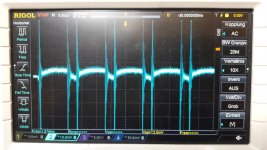
pic 5 is a try to look at the LM317 at 24V psu
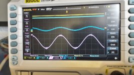
pic 6 is with 28V psu. here is the power consumption about 100 Watt. output of speaker is 2,2,5Ampere with 16,7 Vrms ---> about 37 WATT....clipping so i changed slightly down to 12 o clock at the volume knob...so its no clipping...
my proposal is to keep the volume knob at about 11 o clock. thats the position where the litte "R" is of the front plate after the letter ....FXaudio...
no temp problems because no swee p ...just 1khz tone...🙂
I want to know what is the sensitivity and the "right" position of the volume knob. When is the amplifier clipping....?
I tested the white V5 version of the FX502Spro with the original psu (24V ). this amp is not corrected at the LM 317 for 24V out.
i time i use the 28V rigol dp832.
8 ohms load each channel, 1khz 1Vrms in both RCA in. DMM at R channel to measure the amps
from top to buttom
yellow LM317 in
light blue LM317 out
blue is rca in
pink output at + speaker on the L-channel
pic 1 1 Vrms at RCA in - volume knob at 11 oclock
pic 2 2 Vrms at RCA -typical fixed output from a CD player..e.etc..
its clipping at volume knob 11 oclock
pic 3 2 Vrms at RCA -typical fixed output - no clipping at volume knob 10 oclock
pic 4 1 Vrms at RCA in - volume knob little more then 12 oclock - start clipping. its about 1,789 Amps and 13Vrms ---> about 23 Watts each channel
pic 5 is a try to look at the LM317 at 24V psu
pic 6 is with 28V psu. here is the power consumption about 100 Watt. output of speaker is 2,2,5Ampere with 16,7 Vrms ---> about 37 WATT....clipping so i changed slightly down to 12 o clock at the volume knob...so its no clipping...
my proposal is to keep the volume knob at about 11 o clock. thats the position where the litte "R" is of the front plate after the letter ....FXaudio...
no temp problems because no swee p ...just 1khz tone...🙂
Attachments
-
 FX502spro_v5_1Vrms and 12oclock at 28V psu.jpg145 KB · Views: 121
 -
 FX502spro_v5_1Vrms check LM317 at 24V.jpg158.9 KB · Views: 112
 -
 FX502spro_v5_1Vrms and 12oclock start clipping.jpg156.3 KB · Views: 101
 -
 FX502spro_v5_2Vrms and 10oclock_no clipping.jpg168.8 KB · Views: 110
 -
 FX502spro_v5_2Vrms and 11oclock_clipping.jpg177.6 KB · Views: 598
 -
 FX502spro_v5_1Vrms and 11oclock.jpg122.6 KB · Views: 608
Yes, aircoils do have a huge electromagnetic field. If you don't get problems with electronics near the amp, leave as is.
I've read, you put 1800uF at the AVDD pin with the result of "improves dynamics and transparency." I'm not sure if this is a good idea for the internal regulator structure due to dI/dt (inrush current into the cap) when powering on. There might be effects caused by electromigration which may result in premature fail. I'd rather suggest to keep the values moderate (up to 10uF X7R 50V Ceramic).
You may try to go back to stock value (1uF) and change the cap-value at C_Start is this is related to the internal feedback loop in some case. Former test showed benefits from increased value at this point. 1uF seems to be quite right here, compared to the standard 10nF.
Please see the attached PDF for infos.
hi doctor
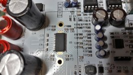
i checked at the V5 white pcb the cap at pin 8 = C_Start (pcb = C20) . i measure 520nF so it looks fine.🙂
but if you look at the pic (zoom in) i see nothing at pin 14 = AVDD??
Am i correct?
thx
chris
Attachments
Last edited:
HI
I checked the post #376 on page 38 --- with some pics of the blue version (v3).
it looks like the 1µF is missing on pin 14 AVDD.
any body out there to confirm this???
should i add a cap?
I checked the post #376 on page 38 --- with some pics of the blue version (v3).
it looks like the 1µF is missing on pin 14 AVDD.
any body out there to confirm this???
should i add a cap?
pin 8 pin 15
pin 9 pin 14
3250mirror3251
AAAHH... thanks
TPA 3250
pin 8 ist C start
pin 9 is AVDD
TPA 3251
pin15 is C start
pin 14 is AVDD
😉
i checked the pin 9:...on the pcb its called C24. I measured 1012nF.
so its fine
thanks irribeo
- Home
- Amplifiers
- Class D
- TPA3250 somebody is listening?